
Pajda
10 kW
I have access to this awfully expensive Micro-TIG system with the hand operated touch retract TIG torch from Amada Weld Tech. At the time, it was one of only two such systems on the market. The other is from Sunstone Welders. Today, such a system has been surpassed by Lasers in virtually every respect. The biggest disadvantage of the Micro-TIG technology is that it is practically unable to weld aluminium.
Micro Arc Welding Torch - MacGregor | Amada Miyachi
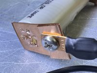
It has a lot of power so it can virtually weld up to 1mm of Cu, but you are practically limited by can thickness of the 18650/21700 format, so you can reliably weld a Cu strips with the thickness of 0.5mm. No additional chemistry is needed, the system automatically brings a protective argon atmosphere thru the torch to the weld spot.
Micro Arc Welding Torch - MacGregor | Amada Miyachi
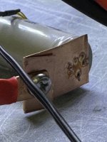
It has a lot of power so it can virtually weld up to 1mm of Cu, but you are practically limited by can thickness of the 18650/21700 format, so you can reliably weld a Cu strips with the thickness of 0.5mm. No additional chemistry is needed, the system automatically brings a protective argon atmosphere thru the torch to the weld spot.
Last edited:
 I haven’t found any practical difference in the performance, accuracies, and response times of type-t thermocouples (versus type-k) but
  ). One of the big lab equipment companies though.
")