TSDZ2 EBike wireless standard (like Specialized Turbo Levo) - OpenSource

Waynemarlow said:
Keep it as simple as possible with minimum input from the user ....
For the first part I agree. As for the second, I hope your job is not related to software development.

This is just a hobby. And we are not saving from it. On the contrary, we spend more money, following our dreams ...
 
plpetrov said:
As for the moment the wireless remote is of no use for me. I do not have and do not plan to use any Garmin devices.
So, why do you want to use the wireless board for?? What are the advantages for you?
 
@rananna,

The remote code really has an issue, it does not work if I keep this line nrf_pwr_mgmt_run(); // idle.
If add instead this lines,
__WFE();
__SEV();
__WFE();

it works.

Next I need to validate using the oscilloscope, if the system is really entering on the low power as also on the ultra low power mode.
 
casainho said:
plpetrov said:
As for the moment the wireless remote is of no use for me. I do not have and do not plan to use any Garmin devices.
So, why do you want to use the wireless board for?? What are the advantages for you?

- No wireless communication for the brake sensors.
- Simple, almost invisible installation on the handle bar.
- No display, that will attract attention if the bike is parked outside.
- Use of the mobile application for performing the configuration and eventually saving it to avoid entering them on each upgrade.
- Use of the mobile application on a phone as display.
- Finally develop a nice and good looking panel screen, using different widgets without the inherited limits from the Bafang displays.
- Have almost unlimited options for gathering statistics, using different visualisation, etc.

I can continue the list if you want. It started to look like users requirements document :)

I really highly appreciate everything that you do. I just have different needs that are just a small fraction of everything you develop. Maybe one day I will buy Garmin bike computer and add the remote also. Before that, I like what you have develop and I prefer it than the standard Bafang displays.
P.S. I had bad experience already ordering two times 860C. They never arrived and I had to open disputes to get my money back. So I consider this as a sign to go for your project :)
 
casainho said:
@rananna,

The remote code really has an issue, it does not work if I keep this line nrf_pwr_mgmt_run(); // idle.
If add instead this lines,
__WFE();
__SEV();
__WFE();

it works.
By "issue" do you mean it is not entering low power mode with nrf_pwr_mgt_run?
 
rananna said:
casainho said:
@rananna,

The remote code really has an issue, it does not work if I keep this line nrf_pwr_mgmt_run(); // idle.
If add instead this lines,
__WFE();
__SEV();
__WFE();

it works.
By "issue" do you mean it is not entering low power mode with nrf_pwr_mgt_run?
The code crash as I reported before and maybe I did comment that line without remember:
casainho said:
I see this when I stop the code:
 
casainho said:
The code crash as I reported before and maybe I did comment that line without remember:
casainho said:
I see this when I stop the code:
more mysteries.
I just debugged that portion of the code on my computer and it works fine.
Is there something different in your debug settings?
 
plpetrov said:
casainho said:
So, why do you want to use the wireless board for?? What are the advantages for you?
- No wireless communication for the brake sensors.
- Simple, almost invisible installation on the handle bar.
- No display, that will attract attention if the bike is parked outside.
- Use of the mobile application for performing the configuration and eventually saving it to avoid entering them on each upgrade.
- Use of the mobile application on a phone as display.
- Finally develop a nice and good looking panel screen, using different widgets without the inherited limits from the Bafang displays.
- Have almost unlimited options for gathering statistics, using different visualisation, etc.
So seems you do not need ANT+ on the wireless board. The ESP32 board would be enough for you. Or, the SW102 display if you would prefer a very small display with the mobile app.

The SW102 firmware has no Bluetooth communications to any app but the firmware could be improved to add support to a mobile app, like the one developed for the wireless board.
 
rananna said:
casainho said:
The code crash as I reported before and maybe I did comment that line without remember:
casainho said:
I see this when I stop the code:
more mysteries.
I just debugged that portion of the code on my computer and it works fine.
Is there something different in your debug settings?
In the past I found problems like this were related to *.ld settings, specifically the RAM allocation.
 
rananna said:
casainho said:
The code crash as I reported before and maybe I did comment that line without remember:
casainho said:
I see this when I stop the code:
more mysteries.
I just debugged that portion of the code on my computer and it works fine.
Is there something different in your debug settings?
I don't know. Can you please ZIP your full project folder and share with me? I will use MELD to compare bot directories and I will even try debug / run your project.

The other difference is for sure the board.
 
rananna said:
rananna said:
casainho said:
The code crash as I reported before and maybe I did comment that line without remember:
casainho said:
I see this when I stop the code:
more mysteries.
I just debugged that portion of the code on my computer and it works fine.
Is there something different in your debug settings?
In the past I found problems like this were related to *.ld settings, specifically the RAM allocation.
Please share your LD file.
 
casainho said:
So seems you do not need ANT+ on the wireless board. The ESP32 board would be enough for you. Or, the SW102 display if you would prefer a very small display with the mobile app.

The SW102 firmware has no Bluetooth communications to any app but the firmware could be improved to add support to a mobile app, like the one developed for the wireless board.

The ESP32 board uses different motor firmware and this way I am losing the compatibility with your firmware and the 850 display I have. Also it requires the use of the original display that I do not like.

The SW102 could be a better options but requires opening to flash the boot loader. Also coming back to your older posts and the current state of other project, I consider the project as almost, if not completely dead.

The wireless board is exactly what I have been looking for. The existence of ANT+ is not an issue and, as I said something I may consider it in the future.

I thought your preference is still to have one project. I think from user perspective it will be better to avoid another fork and have more options. :)
 
rananna said:
rananna said:
casainho said:
The code crash as I reported before and maybe I did comment that line without remember:
casainho said:
I see this when I stop the code:
more mysteries.
I just debugged that portion of the code on my computer and it works fine.
Is there something different in your debug settings?
In the past I found problems like this were related to *.ld settings, specifically the RAM allocation.
Well, I looked into the difference between your code:
Code:
__WFE();
__SEV();
__WFE();
and
Code:
nrf_pwr_mgmt_run();


it turns out that nmrf_pwr_mgmt_run () function simply calls sd_app_evt_wait() if a softdevice is present or __WFE; __SEV; __WFE if the softdevice is not present. That is the only difference.
So, the odd debugging behaviorseems to relate to the presence of the SD.
I guess that is why the reason I chose to use the nrf_pwr_mgmt_run function, but it was so long ago I obviously forgot that earlier today.

see also: https://devzone.nordicsemi.com/f/nordic-q-a/4498/difference-between-wfe-and-sd_app_evt_wait
The sd_app_evt_wait is basically the safe version of WFE when using the SoftDevice. Since the SoftDevice is running in a different context than your application you cannot know if it is safe to use WFE. Therefore, use the SD function

and
https://devzone.nordicsemi.com/f/nordic-q-a/34584/wfe-wfi-and-systemon-mode-differences
System ON mode typically means that the CPU and most peripherals are powered down. However, the low frequency clock and at least RTC0 is active and used for SoftDevice time keeping (assuming you use it), so that the nRF can wake up on a BLE event. It can also wake up on interrupts from any peripheral. To enter system ON low power mode, put the CPU to sleep using WFE or WFI. You can see a short explanation of WFE and WFI in this post. System ON is the most used low power mode,and should be the default state of most applications. You can see that most SDK examples enters system ON low power mode in the main loop. This is typically achieved by calling nrf_pwr_mgmt_run() which calls sd_app_evt_wait() if a SoftDevice is used or __WFE ()if not. (sd_app_evt_wait() itself uses WFE internally).

In system off mode, all clocks and most peripherals are fully disabled. There are only a few limited wake up sources from system off: GPIO, NFC and pin reset. The device always resets when waking up from system off.

https://devzone.nordicsemi.com/f/nordic-q-a/4514/how-to-use-wfe-reliably
If you are using softdevice, use the sd_app_evt_wait(). If you are not using softdevice, use the __WFE()

The softdevice can be in an unknown state during debugging, which may be causing the funny behavior for you.
However, since this is the idle loop, and running often during use, it is obviously not failing when you are not debugging.
so, the failure you are seeing may not be a real issue. Try turning off the breakpoint in the idle loop
 
plpetrov said:
The SW102 could be a better options but requires opening to flash the boot loader. Also coming back to your older posts and the current state of other project, I consider the project as almost, if not completely dead.
SW102 is very small, the wireless board maybe same volume or higher. Open it to solder the wires is probably much easier. Really, now that the mobile app is develop and the firmware is done on the wireless board, adding the part for communication with the mobile app to SW102 would not be that hard... I am busy here, otherwise I could do it.

Anyway, since you are ok for this wireless board, then why not? -- let's do it!!

You mention "Simple, almost invisible installation on the handle bar" - why don't you want the wireless remote? Not that I am trying to convince you but I would like to understand what we should improve.
 
rananna said:
If you are using softdevice, use the sd_app_evt_wait(). If you are not using softdevice, use the __WFE()

The softdevice can be in an unknown state during debugging, which may be causing the funny behavior for you.
However, since this is the idle loop, and running often during use, it is obviously not failing when you are not debugging.
so, the failure you are seeing may not be a real issue. Try turning off the breakpoint in the idle loop

I just compiled the makerdiary board and tried debugging. Failures like you are seeing happen if I put breakpoints in the nrf_pwr_mgmt_run function. It happens every time the debugger stops. Maybe there is a board difference?
But again, is this a real issue?
The debugger runs fine without breakpoints at that particular point and the code also runs fine on the board out of debug mode.
 
casainho said:
Anyway, since you are ok for this wireless board, then why not? -- let's do it!!

You mention "Simple, almost invisible installation on the handle bar" - why don't you want the wireless remote? Not that I am trying to convince you but I would like to understand what we should improve.

There is nothing wrong or nothing to be improved in the wireless remote. It is a very nice idea and may have a great future. There are other people obsessed with the full wireless idea and you will see soon wireless headlights, wireless backlights, wireless lights on the helmets and I do not know what else.

I have nothing against wireless technology. I am using it in home automation and security projects. The main advantage is that you don't run cables. As a disadvantage, I may say that is not so green as every device requires separate battery and even on devices that are monitoring the state of charge I got problems at 50 %. May be due to the high saturation of wireless device in the region where I live, I get from time to time disconnections or communication issues.

Now thinking, we have several options for installing the wireless controller with the three buttons and the multicolour LED:
1. On the handle bar ( what I initially though).
2. On the bike frame somewhere in front using extension cable. Will look nice and on the bigger tube will look smaller. Possible design is a big power button in the middle with the power sign and the LED in the centre. On both sides (up and down) two very small button for plus and minus with the arrow sign.
3. Somewhere near the motor. If used with the wireless remote will be used in rear case for the power on and off functions and in emergency situation to change the asset level or to switch on the lights.

I ordered a bag full all different buttons that may be used for the purpose and it should arrive any moment. I may try to design and print a box with three (or only one button for the users that want a single button). The challenge will be the waterproofing. Also we need to think about the LED as on the two suggested boards, as far as I understood it is in different location. As an option, I would prefer the LED I mentioned. It is easy to solder as it comes already pre-soldered on a small circular PCB with a diameter of 8 or 9 mm.
 
rananna said:
I just compiled the makerdiary board and tried debugging. Failures like you are seeing happen if I put breakpoints in the nrf_pwr_mgmt_run function. It happens every time the debugger stops. Maybe there is a board difference?
But again, is this a real issue?
The debugger runs fine without breakpoints at that particular point and the code also runs fine on the board out of debug mode.
I will need to test without the debugger... I will put a app_timer to blink a LED and then I will quick know if it is working or not.

Meanwhile, could you please test my code? - the makefile has the define for the MakerDiary board:
https://github.com/OpenSourceEBike/ebike_wireless_remote/tree/clean

And my GCC version:
arm-none-eabi-gcc --version
arm-none-eabi-gcc (15:9-2019-q4-0ubuntu1) 9.2.1 20191025 (release) [ARM/arm-9-branch revision 277599]

plpetrov said:
Now thinking, we have several options for installing the wireless controller with the three buttons and the multicolour LED:
1. On the handle bar ( what I initially though).
2. On the bike frame somewhere in front using extension cable. Will look nice and on the bigger tube will look smaller. Possible design is a big power button in the middle with the power sign and the LED in the centre. On both sides (up and down) two very small button for plus and minus with the arrow sign.
3. Somewhere near the motor. If used with the wireless remote will be used in rear case for the power on and off functions and in emergency situation to change the asset level or to switch on the lights.

I ordered a bag full all different buttons that may be used for the purpose and it should arrive any moment. I may try to design and print a box with three (or only one button for the users that want a single button). The challenge will be the waterproofing. Also we need to think about the LED as on the two suggested boards, as far as I understood it is in different location. As an option, I would prefer the LED I mentioned. It is easy to solder as it comes already pre-soldered on a small circular PCB with a diameter of 8 or 9 mm.
What is planned is to use the less components as possible to be easy for DIY. I only see the need of the big button because the original one is to small, I think.
And the original LEDs are great because are very simple to control. For the remote they have even the advantage to be very low power to control, no fancy and long processing power. Also the LEDs should use low power, I guess the Nordic board is done for that since it is ready to be used with a battery only.

For waterproofing the button, maybe there are ones on the market or maybe some black tape on top of the button, since the tape is flexible.
 
casainho said:
Meanwhile, could you please test my code? - the makefile has the define for the MakerDiary board:
https://github.com/OpenSourceEBike/ebike_wireless_remote/tree/clean

And my GCC version:
arm-none-eabi-gcc --version
arm-none-eabi-gcc (15:9-2019-q4-0ubuntu1) 9.2.1 20191025 (release) [ARM/arm-9-branch revision 277599]

Ok , I will try to get to it tomorrow.
 
rananna said:
casainho said:
Meanwhile, could you please test my code? - the makefile has the define for the MakerDiary board:
https://github.com/OpenSourceEBike/ebike_wireless_remote/tree/clean

And my GCC version:
arm-none-eabi-gcc --version
arm-none-eabi-gcc (15:9-2019-q4-0ubuntu1) 9.2.1 20191025 (release) [ARM/arm-9-branch revision 277599]

Ok , I will try to get to it tomorrow.
Reviewed. A PR has been created incorporating the changes
 
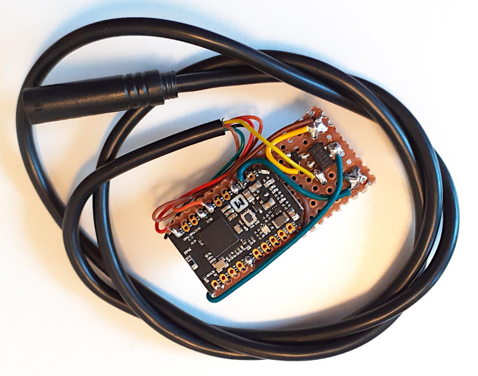
I assembled a TSDZ2 wireless board and took pictures for future documentation / ideas (sorry, I don´t have yet with me the Nordic board). Everything worked for the first time. In the end I flashed the Bluetooth bootloader and then flashed the firmware using the bootloader.

To save the volume, I put the wireless board under the DC-DC converter. The USB area that I cut to the wireless board was then enough to give space for the only 2 other components: the mosfets.

I can confirm that all the circuit work (I verified the mosfet circuit, they correctly enable the voltagle to TSDZ2). I was not able to ride but I saw the TSDZ2 motor providing data, like pedal cadence and pedal side.

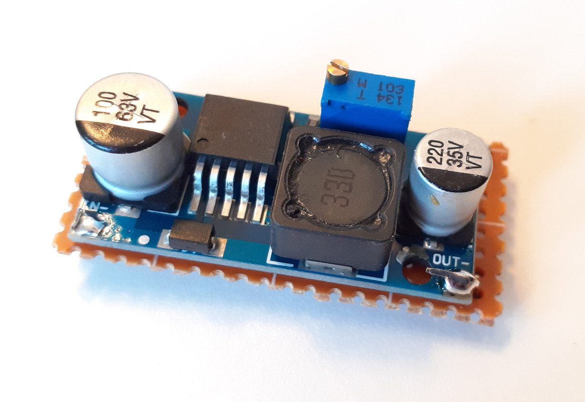
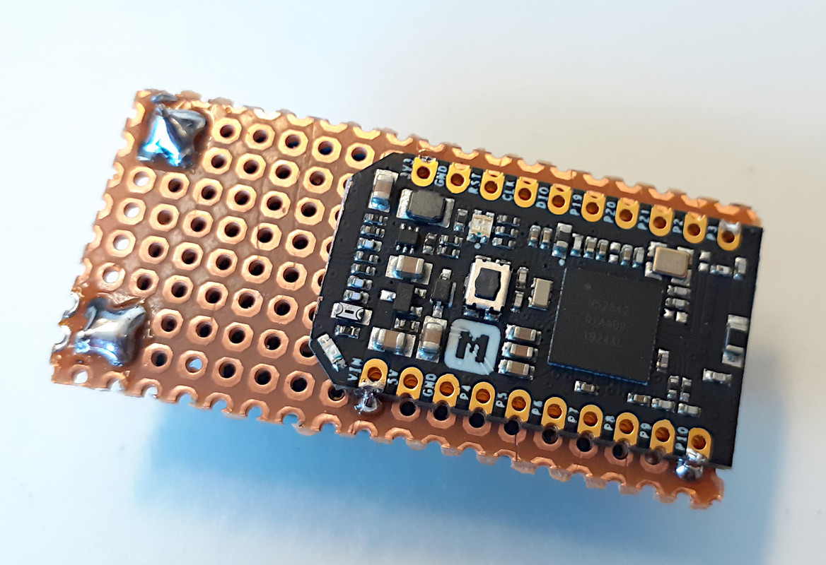
I used a perfboard to hold both the DC-DC converter on one side and the wireless board on the other, including the 2 mosfets and the connections:
TSDZ2-wireless-board-01.jpg


TSDZ2-wireless-board-02.jpg


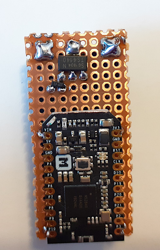
Here a picture of the 2 mosfets soldered. One is very small but it is perfectly ok to solder like this:
TSDZ2-wireless-board-03.jpg


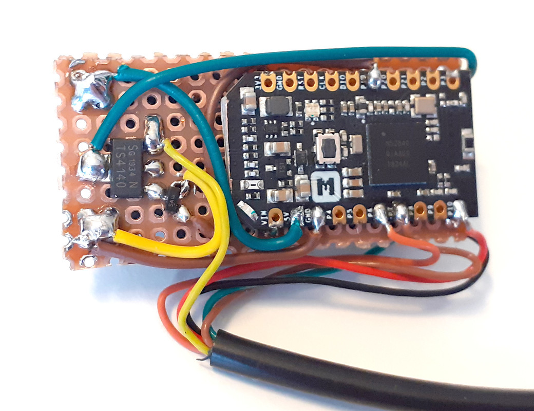
Now with the final wires soldered:
TSDZ2-wireless-board-04.jpg


The board is quite small, here the final cable to connect to TSDZ2 display connector:
TSDZ2-wireless-board-05.jpg


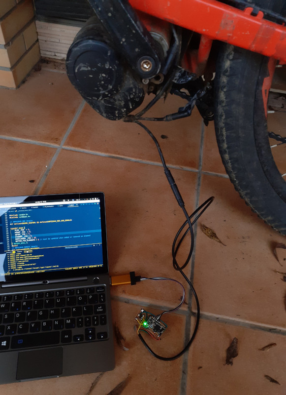
And after I soldered the wires for STLinkV2 and connected to my PC, so I could flash the Bluetooth bootloader:
TSDZ2-wireless-board-flashing-bootloader.jpg


And finally testing by connecting the mobile app as also the Garmin GPS display. I did not ride by I rotated the pedals a few times and everything was working as expected - I could the the pedal cadence and pedal side on the phone:
[youtube]AklWXqSHkPU[/youtube]
 
casainho said:
]

The board is quite small, here the final cable to connect to TSDZ2 display connector:

And finally testing by connecting the mobile app as also the Garmin GPS display. I did not ride by I rotated the pedals a few times and everything was working as expected - I could the the pedal cadence and pedal side on the phone
Wow! Congratulations!
That must be very satisfying after all those months of development!
We are on the other side of the hill now ; it won't take too much additional work to add the missing elements. ( Brakes, enclosures, throttle?, Pwr control etc)
 
rananna said:
casainho said:
]

The board is quite small, here the final cable to connect to TSDZ2 display connector:

And finally testing by connecting the mobile app as also the Garmin GPS display. I did not ride by I rotated the pedals a few times and everything was working as expected - I could the the pedal cadence and pedal side on the phone
Wow! Congratulations!
That must be very satisfying after all those months of development!
We are on the other side of the hill now ; it won't take too much additional work to add the missing elements. ( Brakes, enclosures, throttle?, Pwr control etc)
On the firmware side, mobile app and remote, there is something missing. I need to implement a turn on and turn off command of the TSDZ2 motor, where at each turn on, the motor controller will initialize: send back the firmware version, configurations and calibrate the torque sensor. There must be some state machine on the wireless board firmware and them other state machine on both mobile app as also on the remote. I will start on the mobile app, even because I need to add brakes and lights state to the mobile app.
 
casainho said:
I can confirm that all the circuit work (I verified the mosfet circuit, they correctly enable the voltagle to TSDZ2). I was not able to ride but I saw the TSDZ2 motor providing data, like pedal cadence and pedal side.

Here a picture of the 2 mosfets soldered. One is very small but it is perfectly ok to solder like this:

Excellent news! The only thing I can see that looks different to what I did is that I connected both Vbb pins (2+4) on the 4140 whereas looks like you've only connected to pin 4. Shouldn't make any difference - but i'll give it a go that way just in case... :)
 
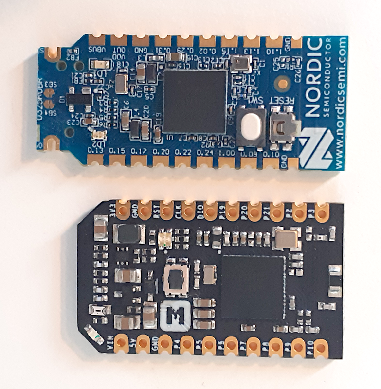
I received the new boards:

image.png


And I will use next days to develop TSDZ2 wireless firmware for being able to turn on / off the motor, based on a command sent by the mobile app (will need to later be implemented also on the wireless remote). I will also need to develop the mobile app to have the button or option to turn on / off the motor.
 
@rananna and other developers,

I burned 2 times a wireless board, while it was connected to my PC using the STLinkV2 clone and the also connected to the 58V of battery, provided by the the motor controller LCD connection. The board did work for some time and I think the issue may happen when connecting / disconnecting the battery power to the motor controller.

We need to better understand this issue, as at least the final user will need to connect the wireless board to PC using STLinkV2 when flashing the bootloader....

I got the firmware ready for turn on / off the TSDZ2 motor controller, a simple command from Bluetooth or ANT will do it. Next I will implement this on the mobile app and when it is working, then we can implement on the wireless remote.
 
Back
Top