• Hello ES! We could use some help to get us past the finish line on building the new knowledgebase for the forum.
    Can you donate? Please see our fundraising page. Thank you!

VESC for Bafang M560

Status
Not open for further replies.
The Bafang M560RS torque sensor looks somewhat close to Not CANbus version.
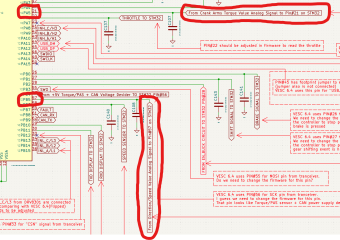
I can confirm that for the M510, it has the analogue version obviously:
1760717621873.png
1760717752517.png


Looking at the datasheet, PC10+PC11 have no timer function, that would be expected for a quadrature signal, but UART or SPI function. So the signals have to be read by polling or an EXTI interrupt :eek:
On the hub motor controller, this two wires from the torquesensor are not connected at all 😵‍💫

1760718201361.png

The PA15 pin has a kind of square wave signal, when the pedal rotates. I guess, you can get the candence signal from the time between the rising edges :unsure:
1760726511973.png
 
Last edited:
So I guess we can ignore the PC11 pin and PC10 pin signals and do not connect them and use only PA7 pin (for torque) and PA15 pin (for cadence). I do not know if we need rotation direction information, we might need it for safety reasons, but we could ignore it if we can not obtain it and hardcode it in firmware if the cadence is more than 0 the direction of rotation is always forward if necessary.

Is there any way to tell how the VESC firmware Benjamin Vedder wrote for the Innotrace X1 controller (which uses UART torque sensor) uses the PA5 pin (torque value) and PB5 pin (cadence, direction values) lookin on this Github page?


1760732380185.png

As I understand if Benjamin Vedder figured out the algorithm for such torque sensor signals and we just can set the pins on the MCU for those signals and copy the VESC for Innotrace code to Luna firmware to make the M560/510 torque sensor works?
 
Last edited:
Innotrace code to Luna firmware
Why?! You can use the Luna code for the cadence as it is. You just have to read the analogue torque signal from ADC2 instead from the CAN message, see my Flipsky implementation...
The pins I mentioned in #26 are for the original Bafang processor, not the Luna VESC...
The Luna M600 uses PB0 for ADC2
 
Last edited:
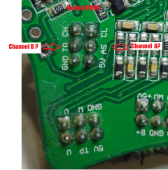
What is ADC2? Is it a pin on the STM32 chip? Or it is some kind if entity in the VESC/Luna firmware code? Or both?

Meanwhile I made an extension cable for the torque sensor and connected Bafang M600 torque sensor to the Lina M600 controller installed in the M560RS just to double check the issue is not the 3D printed adapter and the adapter does work and spins the motor with M600 torque sensor.

Here is an important observation - the Luna M600 uses the cadence and direction information from the torque sensor besides the torque information. If I apply torque and do not rotate the crank the motor does not spin. If I apply torque and rotate the crank on wrong direction the motor does not spin. The motor starts spinning only if 3 conditions are achieved: The torque is applied, the crank shaft rotates, the crank rotates in the correct direction. So the controller firmware uses all 3 parameters from the PAS/Torque sensor - torque, cadence (or cadence is not equal zero maybe), cadence direction.

1760835261073.png
 
Last edited:
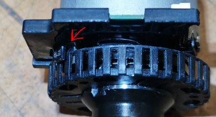
OK, I extracted the torque sensor from theM560RS motor and it looks like the cadence signal goes from the optical sensor. There is a plastic shroud with openings block the optical sensor emitter and receiver sides. I am not sure if this sensor is able to define the direction of rotation. It might be M560RS firmware does not use it and consider if torque signal above 0 and the cadence is above 0 then it rotates in the correct direction.

But it could be actually 2 optical sensors shifted a little against each other so you can define the rotation direction depending on which one receives the signal first. But I think this is just one C-shaped optical sensor with emitter and receiver because of if I look close it loos like they have mutual base and look slightly different.

1760843785533.png

1760843844771.png


It also looks like the regular M560 (not RS) torque sensor uses magnetic sensor with metal ring with slots instead of optical sensor with plastic shroud.

1760844273541.png
 
Last edited:
It looks like we are completely cooked guys. I was hoping we can fit M600 torque sensor to M560 motor to make the VESC Labs for Bafang M560 controller works at least that way (and maybe 3D print a simple adapter to fit it properly) so you can just install M600 torque sensor with the controller but it turned out the M600 torque sensor left side bearing mating surface is lower than this mating surface on M560 torque sensor. That means M600 toque sensor does not fit M560 motor case and there is no easy way to make it fits without the motor case modification or differed narrower bearing and probably an adapter for such bearing. At this point you just better purchase M600 motor and build the VESC for Bafang M600 controller.

1760846855424.png

With that being said I am not sure if there a reason make an M560 motor controller if the torque sensor does not work. How do we make the M560 torque sensor works with this VESC controller is a good question. It looks like there are only two persons who have the competence to figure this thing out, Krasnodar (well, it looks like he already figured it out) and Markos. But unfortunately none of them is willing to assist the e-bike community with this project.

So if someone is really interested to build and use this controller and knows that VESC firmware thing at the same time here is what I can do. I can reverse engineer the torque sensors connection circuits on the Bafang M560RS controller I have so we can see where exactly this torque sensor is connected to the MCU and guess what kind of signals it sends to it. I also have a multimeter so I can measure voltages and resistances if it is something how this torque sensor communicates with the MCU. I can implement the m560 torque sensor circuits on the VESC Labs M560 PCB, but those circuits are likely going to be connected to different pins on STM32 (comparing with Bafang M560RS controller MCU) becasue of other pins are likely occupied with other things Luna controller uses (I need to dig deeper into it and see what is awailable. We have awailable pins on MCU from the original M600 torque sensor connections, plus we removed Bluetooth and USB so we might use those in addition if necessary). But all this stuff does not make sense if we do not have an involved person who knows the VESC firmware and such. Without this it is going to be just another throttle only VESC. It looks like qwerkus was interested in VESC for Bafang M560 controller and might know that VESC firmware thing, but I am not sure if he is still interested in it.

Let me know what you think guys.
 
Last edited:
I got promising news for you guys! Bafang M560RS works with good old Bafang M620 UART torque sensor!

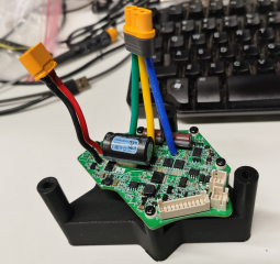
I got a semi broken Bafang M620 UART torque sensor laying around and since the torque sensor circuits on the Bafang M560RS controller looks somewhat close to Innotrace X1 controller (which also looks like a copy of Bafang M620 UART torque sensor circuits) I decided to give it a try. I 3D printed a jig for the M560RS controller, installed it on the motor, connected the Bafang M620 UART torque sensor and it works!

So it looks like Bafang M620 UART torque sensor sends the same signals from those two pins I mentioned earlier. And if Benjamin Vedder already implemented this torque sensor in the VESC Innotrace X1 firmware and we also have completely reverse engineered Innotrace X1 controller we can simply copy the torque sensor circuits from the Innotrace X1 controller and copy what Benjamin Vedder did in his firmware for the Bafang M620 UART torque sensor. But we still need the person who knows the VESC code and all that firmware things to implement this in the firmware.


1760855815201.png

1760855883128.png
 
Last edited:
I disconnected these two pins from the torque sensor connector and both Bafang M620 UART and M560RS torque sensors do not spin the motor with those pins disconnected.

1760859302537.png

1760859716379.png

1760859362799.png

On the Bafang M620 UART controller and on Innotrace X1 controllers those pins are not connected to the MCU while on Bafang M560RS those pins are connected to MCU. Maybe they can not be simply disconnected but have to be connected like on M620 UART and Innotrace X1 to make the torque sensor works. Well, we know for sure M620 UART troque sensor works this way with M620 UART controller and with Innotrace controller. But I am not so sure if M560 torque sensor will work this way.

1760859187389.png
 
What is ADC2? Is it a pin on the STM32 chip? Or it is some kind if entity in the VESC/Luna firmware code? Or both?
You not seem to be familiar with VESC controllers ;)

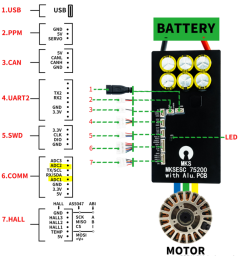
ADC2 is called a pin on a header on almost all VESC hardware. ADC1 is used for the throttle and ADC2 for linear regen braking normally. It is implemented in the ADC app by default. So we can use this ADC input for the torque singal as a middrive can't brake with regen anyway. If you are still planning a new board layout for a "M5xx-VESC" you should connect the torque signal of the sensor with the PB0 pin of the processor. See #28
Of course you have to compile the Luna M600 firmware with the changed logic in the PAS app. But that's a matter of 5 minutes, just one single line of code has to be changed. You don't need a Krasnodar or a Marcos for this minimal modification. :whistle:

1760860894387.png
 
Last edited:
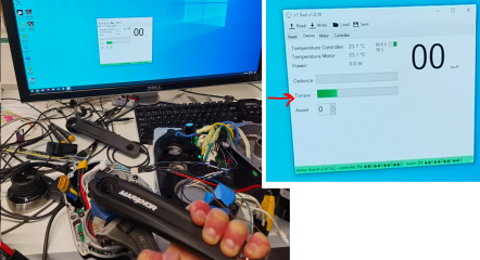
Guys, it seems to be we are on the right track! The Bafang M560RS torque sensor works with Innotrace X1 controller! The torque sensor pinout and wires colors posted above is also correct.

I opened my M620 motor with Innotrace X1 controller and connected the Bafang M560RS torque sensor to it. Connected Innotrace controller to computer with FDTI chip USB dongle and launched the Innotrace X1 Tool application and in the Motor menu tested the torque, cadence and direction and it works!

It also works with disconnected PAS1 and PAS2 pins. I also disconnected the Torque pin and the application stopped measuring torque but measured the cadence/direction. Then I disconnected the cadence/direction pin and connected the torque pin back and it measured only the torque only. So everything works and pins functions are the same as on old Bafang M620 UART torque sensor.

1760919217025.png

1760919427045.png

1760919538660.png
 
Why?! You can use the Luna code for the cadence as it is. You just have to read the analogue torque signal from ADC2 instead from the CAN message, see my Flipsky implementation...
The pins I mentioned in #26 are for the original Bafang processor, not the Luna VESC...
The Luna M600 uses PB0 for ADC2

But PB0 pin is occupied with BRAKE signal on the Luna controller we use for reference. It would be nice to keep this function especially for the motor with extra power.

And we still need to connect the cadence signal somewhere because of without cadence signal the motor will not spin just with torque signal alone. We could probably hardcode it to make cadence always above 0 so the motor will start spinning as soon as MCU sees the torque but that is probably not a good idea for a powerful motor. Plus the cadence signal can be used for perfecting the motor control to make the pedaling less jerky between the strokes. I do not know how Luna processes it for such purpose though if it does it at all (but Luna controller feels like it has some smoothening between pedal strokes, maybe it is constant parameter regardless of cadence, hard to tell).

1760926759001.png

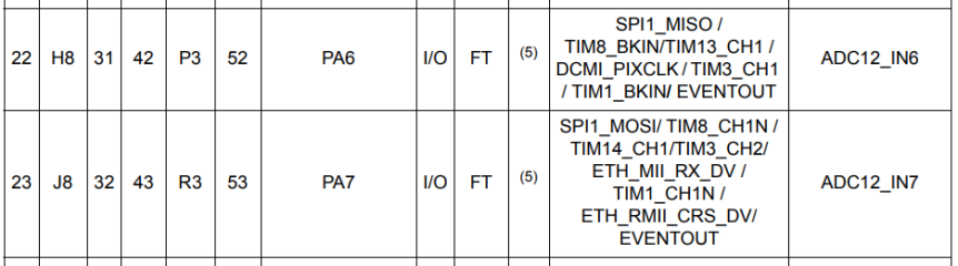
Is it possible to reuse the PA6 and PA7 pins for the Torque and Cadence/direction signals? Luna uses those pins for those quadrature signals. I guess this is Analogue to Digital Conversion (ADC) function so as I understand those pins can be used for Torque and Cadence/direction signals. Or it is too much work to adjust the VESC/Luna firmware for such connection?

1760926979141.png

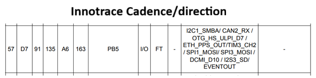
Here is the list of functions of the pins Innotrace uses. I do not see ADC function on the Cadence/Direction signal pin on the Innotrace controller though. Maybe it defines the cadence by different means.

1760927413545.png

1760927544515.png

Here is the list of functions of the PA6 and PA7 pins we can repurpose on the new VESC for M560 controller for Torque and Cadence signals (those are currently used for quadrature signals from PAS sensor).

1760927710459.png
 
Last edited:
But PB0 pin is occupied with BRAKE signal
Yes, as written before ADC2 is used for linear regen braking in the VESC. But it make no sense to use an analogue input for a digital brake signal. You can use any other digital GPIO pin for the brake switch.

And we still need to connect the cadence signal
?! As written before also, you can keep it as it is, you just have to adapt the different pinout on the torque sensor connector for PAS1 and PAS2.
 
Please correct me if I am wrong. You are saying pin "PAS1" should be connected to pin PA6, pin "PAS2" should be connected to PA7, pin "Torque" should be connected to PB0, and pin "Speed/Direction" should not be connected to anything?

So PAS1 and PAS2 on the Bafang M560/510 torque sensor are the pins for the same quadrature signal as other two pins on CANbus Bafang M600 torque sensor? I was thinking PAS1 and PAS2 are useless pins on Bafang M560/510 torque sensor.

1760943009389.png

So it looks like those PAS1 and PAS2 pins are A and B channels of the optical encoder I posted above? (Well, to be precise on your diagram the pin PAS1 is channel B, and the pin PAS2 is channel A if Bafang did not change it)

1760948415555.png

 
Last edited:
Is there any way to define which pin on the STM32 is for channel A and which pin is for channel B of the quadrature signals PAS sensor looking on the VESC/Luna firmware?


The markings on the Bafang M600 controller I found in the Internet on the torque sensor connector are different. They look like AS and TR (or maybe TB).

Or it is easy to swap the channels in the VESC firmware (or change the rotation direction rule) in case I connect them opposite way?


1760982406280.png
 
Yes, as written before ADC2 is used for linear regen braking in the VESC. But it make no sense to use an analogue input for a digital brake signal. You can use any other digital GPIO pin for the brake switch.
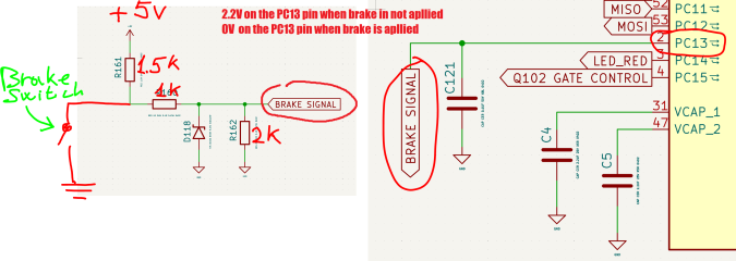
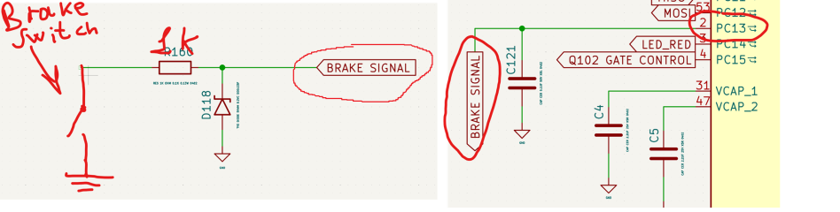
We have PC13 pin which is not connected to anything on the Luna M600 controller. I guess it will be the easiest way to use that pin for the brake function.

So the brake switch shortens the brake circuit to ground when the brake is applied. That should turn the motor off (just turn the power off, no regenerative braking).

The voltage divider circuit maintains about 2.2V on the PC13 pin when the brake is not engaged and the motor should work as usual. When the brake is applied the voltage on the PC13 pin drops to 0 and the firmware should turn the power off when such condition exists. But it should start works as usian as long as the voltage on that pin is back to 2.2v (or slightly less). I guess we need to make a little margin, like the motor power turns off when the voltage on that pin is below 0.5V and the motor start working normally when the voltage on that pin is above 1V.

Is it possible to program this function for the VESC/Luna firmware for the PC13 pin?

Please also note the PC13 pin have some limitations. I do not know what maximum load of 30 pF means. And the note 4 also looks scary. Maybe we can not use this pin for such function.

1761012228184.png

1761013778506.png

1761012514734.png

1761011217515.png


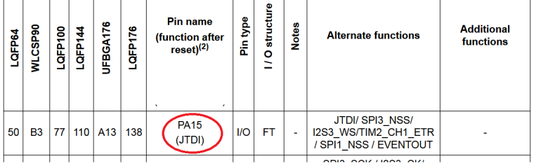
If using that pin for brake function is a bad idea then the only option is to repurpose the pins were used for different stuff. Like we can connect that brake circuit with the voltage divider to PA15 pin for instance. Luna uses that pin for programming the integrated Bluetooth module through STM32. But since we removed the Bluetooth module from the PCB we can use that pin for the Brake function. I do not know if it is difficult to suppress the original integrated Bluetooth programming function of this pin in VESC/Luna firmware and program new Brake function for it

1761012605032.png

1761012925897.png

Let me know guys which way we should go
 
Last edited:
Is it possible to program this function for the VESC/Luna firmware for the PC13 pin?
This is the commit for the digital break function, that I've implemented in my Flipsky project. No witchwork. You don't need an extra pullup resistor, you can use the internal pullup function of the processor. A little RC filter for debouncing may be useful.
 
Last edited:
This is just a reply to some random deductive reasoning i saw above(about 2.2V);
Can't do anything with just "some voltage" on a pin, it'd need to be converted, which the mcu is apparently
unable to do for that pin(there would be something like "ADCxy_INz" in alternate functions for it, if it could,
but pc13 is 'special' anyway), so it is safe to assume the pin is used as io w/logic level(TTL in this case, i guess,
but the point is, it can be only off/low/0 or on/high/1 however you name the state(would be "active low" when
0 means "brake is on")).
 
Oh, just noticed that you're apparently mixing datasheets. That doesn't really work in the world of mcus.
Especially not when the manufacturer has published their own(==can't use the datasheet for stm32f4xxx
with gd32f303xxx for example).
 
This is the commit for the digital break function, that I've implemented in my Flipsky project. No witchwork. You don't need an extra pullup resistor, you can use the internal pullup function of the processor. A little RC filter for debouncing may be useful.
You mean I can make the brake circuit for the PC13 pin like this?

1761027282882.png
 
Oh, just noticed that you're apparently mixing datasheets. That doesn't really work in the world of mcus.
Especially not when the manufacturer has published their own(==can't use the datasheet for stm32f4xxx
with gd32f303xxx for example).
That picture with gd32F303xxx is just to demonstrate the circuits the Bafang controller uses with this MCU. We are going to use stm32 and stm32 pins functions.
 
This is just a reply to some random deductive reasoning i saw above(about 2.2V);
Can't do anything with just "some voltage" on a pin, it'd need to be converted, which the mcu is apparently
unable to do for that pin(there would be something like "ADCxy_INz" in alternate functions for it, if it could,
but pc13 is 'special' anyway), so it is safe to assume the pin is used as io w/logic level(TTL in this case, i guess,
but the point is, it can be only off/low/0 or on/high/1 however you name the state(would be "active low" when
0 means "brake is on")).
So as I understand that PC13 pin can not read the voltage precisely and can only set it's state to 1 if the voltage on that pin is 3.3V and 0 if the voltage on that pin is 0. Then we need different circuit provides 3.3V when brake is no applied and 0V when the brake is applied. As I understand stancecoke said the state of that PC13 pin can be set to 1 when it is not connected to ground somehow through the VESC firmware so I guess we can just connect that PC13 pin through maybe 1 KOhm resistor to the brake switch without applying 3.3V externally to that pin.
 
Last edited:
As I understand @stancecoke said the state of that PC13 pin can be set to 1 when it is not connected to ground somehow through the VESC firmware
This is a basic function of the STM processors, you can configure each GPIO pin to activate the internal pullup resistor.
The configuration is done in this line:
https://github.com/stancecoke/VESC_...1f48818bfde/hwconf/flipsky/hw_75_100_V2.c#L54
If you use CubeMX to configure your hardware you can choose the pullup/pulldown function by the drop-down menue.

1000
 
Last edited:
Alright guy. I think we figured out the circuits for the new M560 torque sensor and finished the schematics of the M560 VESC controller. Since we did a good progress here is the first release files for this milestone. Feel free to review the torque sensor connection and let us know if you see any issues.

[ trademark infringing archive removed ]

The KiCAD 9.0.0 project file can be found in the 7-Zip archive here

1761089623371.png

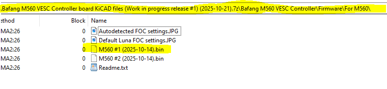
The firmware I dumped from the STM32 after making the Luna M600 controller works with the Bafang M560 motor can be found here. Everything works except the torque sensor. This firmware also should work with the new VESC Labs for Bafang m560 controller when we get the controller done but we hope we will make another VESC/Luna firmware for it which will allow to use M560 Torque sensor.

1761089835504.png

The PCB layout is in progress. The power stage layout is mostly complete. The 12V power source layout is complete. The controller turning On and Off circuits layout is complete. Roughly defined the new spots for the gate drivers chips. Since we gained some room on the PCB removing the Bluetooth module and USB connector the small legless gate drivers chips package changed to the bigger package with legs for easier soldering and better thermal performance.

1761090414099.png

1761090548360.png

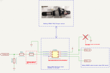
If you don't want to download the files here is essentially the new torque sensor connections and changed brake connection. Let me know if you see any issues.

1761090818541.png

1761090976505.png

1761091077369.png

1761091141522.png
[ trademark infringing image removed ]
 
Last edited by a moderator:
Status
Not open for further replies.
Back
Top