VESC for Bafang M560

Status
Not open for further replies.

TPEHAK

🚴‍♂️ Mega poster
Joined
Jun 9, 2023
Messages
905
Location
Twin Peaks
Moderator note: this is not a VESC Labs controller and the poster falsely claimed to be part of the VESC project. See the last couple pages of this thread for discussion about the infringement and why this decision was made.


The archive with the current versions of the motor controller files (KiCAD version 9.0.0), Gerber files and firmware files can be downloaded here (updated on 2025-11-24)

[ trademark infringing archive removed ]

[ trademark infringing image removed ]

[ trademark infringing image removed ]

The archive file with Gerbers for PCB ordering

1762229333081.png


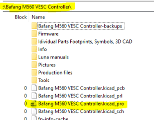
The KiCAD project file location

1762229005554.png

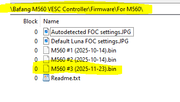
The latest firmware file location

1764044762080.png


The thermal pad cutting template file location

1762229133147.png

How to order the motor controller PCB on JLCPCB.com



How to order parts for the motor controller PCB


How to flash the firmware file onto the motor controller


Cable for firmware flashing (follow the pinout from the motor controller KiCAD files to connect ST-Link dongle, it is different comparing with what shown in this link!)



How to connect VESC Express dongle to setup motor with VESC Tool application through USB cable or Bluetooth ot WiF and to calibrate the rotary encoder


How to calibrate the rotary encoder


It looks like it is about time to start the dedicated tread.

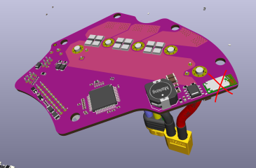
Since I have a Bafang M560RS motor laying around I think it is a good idea to design an open source VESC Labs motor controller for it.

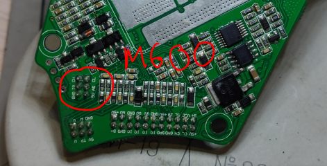
It turned out the Luna M600 motor controller PCB does not fit Bafang M560 motor because of different locations of the mounting holes and components interference.
 
Last edited by a moderator:
Since I have a Bafang M560RS motor laying around I think it is a good idea to design an open source VESC Labs motor controller for it.
What will be the advantage in comparison to the original controller?!
I can't understand that VESC hype. 🤷‍♂️
Spend your time and skills in reverse engineering the Bafang controller hardware, then you can upgrade your bike with less than $10 for a SWD programmer.

Would be very interesting, where the encoder pins are going to on the processor. That's the information that's missing for me recently.
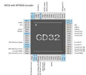
I only identified the quadrature pins A and B (PC6+PC7) so far, Z and PWM are missing. The encoder sends the signals, I've checked that with the scope.

1760084242906.png
 
Last edited:
I can check if the pins are connected to the processor when I will have time if you can not find it. If you have a multimeter you can sharpen the probes with sandpaper (it is necessary because of the Bafang PCB has conformal coating), set the multimeter in ringing mode and stick one probe to the pin of the encoder slightly twisting it like a drill (otherwise it might not make connection because of the coating), then stick other probe near it the same way to make sure it has connection, then start sticking one probe to each pin of the processor one by one the same way slightly twisting it (you might need double check with other probe you penetrated through the coating and have connection with the processor pin). You might need to do this under microscope.
 
Last edited:
That's quite tricky as the encoder is on the opposite side than the processor. So you have to find the proper vias first...
 
If the components are on opposite sides of the board I usually stick a probe to the pin and hold the probe and the PCB by one hand keeping the probe engaged with the pin and use other hand pocking the probe on the opposite side of the board. It is tricky.
 
What will be the advantage in comparison to the original controller?!
I can't understand that VESC hype. 🤷‍♂️
Spend your time and skills in reverse engineering the Bafang controller hardware, then you can upgrade your bike with less than $10 for a SWD programmer.

Would be very interesting, where the encoder pins are going to on the processor. That's the information that's missing for me recently.
I only identified the quadrature pins A and B (PC6+PC7) so far, Z and PWM are missing. The encoder sends the signals, I've checked that with the scope.

View attachment 378864


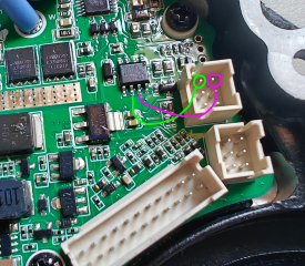
OK, I checked the Bafang M560RS controller I have and it looks like the rotary encoder is connected different way. It is not connected directly, there are resistors going on between. I do not know if it is helpful for you but here it is.

1760216671379.png


What will be the advantage in comparison to the original controller?!
I can't understand that VESC hype.

The original controller is not capable of high voltage an hing power. We need more voltage, more power, more juice.

I personally do not care if it is going to be VESC or something else, it just happened we have a good VESC reference does not require much work.
 
Last edited:
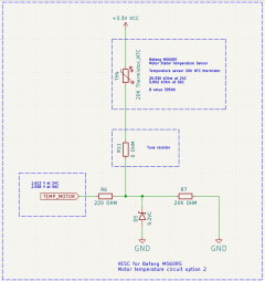
Guys, we got a situation. Bafang M560RS uses different motor stator temperature sensor incompatible with Luna controller. M600 uses 1K PTC thermistor, but the M560RS motor I got uses 20K NTC thermistor.

Can anyone confirm if regular Bafang M560 (not RS) uses same 20K NTC thermistor for the motor temperature? You can just measure the resistance between the temperature sensor connector pins with multimeter at room temperature.

I also remember somebody on the VESC Discord in the Innotrace reverse engineering thread posted a link to the Luna firmware motor temperature sensor code (it was just a list of voltages and corresponding temperatures). Anyone knows the link to that thing?


1760303707439.png


1760244605956.png

1760244652482.png

1760244735872.png

I did a band aid to trick it but we need to sort this mess out

1760247674121.png

1760247724429.png
 
Last edited:
It is not connected directly
Sure, there are RC filters on every input line. That's usual. Thank you for checking! (y)

We need more voltage, more power, more juice.
Middrives were invented to bring fat men with little effort uphill with legal "250W continous output power". If you want go in the range 2-3 kW, a middrive with a common draillieur makes no sense. The chain and sprocket will wear out faster than you can say “boo.” You don't need a gear shift in this power range. A hub motor will push you up any ascent. No commercial electric car or motorcycle has a gear shift. But it's your hobby, so have fun ;)
 
Last edited:
That's good. So it loos like both M560 and M560RS use the same thermistor.

OK, we have two options.

Option #1 is we can just keep the Luna circuit but change the resistors values to match 20K NTC thermistor. But we will likely need to change the temperature detection algorithm in firmware which might be complicated because of now the voltage goes down as the motor temperature rises. But in case of we can not change the firmware we will have at least ability to purchase a 1K PTC thermistor, solder same resistors to the PCB as on the Luna M600 controller, glue the thermistor somewhere inside the motor, plug it to the PCB and make it works with the original Luna M600 firmware without changing the PCB.


1760304558491.png


Option #2 is we can change the circuit and match the Lune M600 with PTC thermistor logic (voltage rises and temperature rises) and it is probably going to be easier to change the firmware (maybe it will require just changing the voltages to temperature matching values in the code). But in case we will not be able to modify the firmware even this way we are cooked because of the PCB will not work with 1K PTC thermistor without PCB modifications.


1760305053462.png

I also was not able to find this temperature sensor menu in the VESC tool application on the phone. So do not know if it is possible to make it works using just VESC Tool application, it will likely require changing the firmware code


What do you think guys, which way we should go? Anyone is familiar with how to change the VESC code and compile the VESC firmware?
 
Last edited:
Modifying the software code will probably be necessary, as apart from the temperature sensor we also have another strain gauge sensor and another speed sensor.
 
I also was not able to find this temperature sensor menu in the VESC tool application on the phone. So do not know if it is possible to make it works using just VESC Tool application, it will likely require changing the firmware code
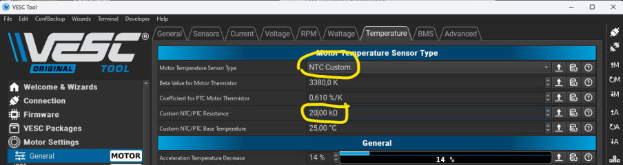
The VESC tool has the "NTC Custom" option, you can set all details yourself. So no need to compile your own firmware

1760366441917.png
 
The VESC tool has the "NTC Custom" option, you can set all details yourself. So no need to compile your own firmware

View attachment 379067
Holy cow! It works! You are right!

I just connected the controller PCB with USB to the computer, launched the VESC Tool application on the computer, connected the controller in the VESC Tool application and adjusted the settings in the "Motor Settings"-->"General"-->"Temperature" menu and uploaded it to the controller.

Here are the correct settings for the Bafang M560 temperature sensor

1760385853141.png

At room temperature

1760385996527.png

After warming in the dryer

1760386046917.png

So we do not need to change anything in the temperature sensor circuit or firmware!
 
Last edited:
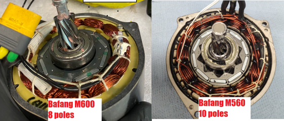
OK guys, we got another problem. I just realized Bafang M600 and M560 have different amount of poles of the rotor. Bafang M600 has 8 poles, but Bafang M560 has 10 poles.

1760413115586.png

I attached Luna M600 controller on the M560 motor, calibrated the rotary encoder (it looks like the rotary encoder calibration went OK), but it does not spin (it just jerked a little at the beginning when I actuated the throttle and then it stopped with buzzing sound. And after this it just makes buzzing sound when I push the throttle but does not spin. I also can see on the gauges the amperage rises when I push the throttle).

Anyone knows how to setup the controller with the VESC Tool for this motor (preferably with the mobile application on the phone) without messing other settings up (I tried to setup the motor and it looks like it messed all the functions, like encoder does not calibrate anymore after this, all sorts of errors on the display, no reaction on the throttle, I am sure the torque sensor does not work too after this).

And I guess it is not just simply changing the poles in the VESC Tool, I am sure other parameters should be adjusted too, but how?

This is what the VESC Tool reads from the Luna M600 controller by default. But M560 motor is different (different amount of magnets/poles, different windings, different wires).

1760413715905.png

I flashed the Luna M600 firmware back, connected with USB, launched VESC Tool and set 10 poles. But it does not work anyway (same way as with 8 poles making buzzing sound and does not spin). How do I make it works?

1760413971388.png


1760415812418.png
 
Last edited:
OK, I connected it with USB to computer and used VESC Tool to set 10 poles and detect FOC. Id does not rotate in "Encoder" mode. But If I set it to "Sensorless" it does spin. Encoder calibration does not help. How do I fix it? We need the encoder.

1760423152455.png

Here are the encoder settings. Should I change it somehow? Is it somehow paired with amount of poles?

1760423713722.png

1760423841397.png
 
Last edited:
I think we did it guys! Luna M600 works with encoder now on the Bafang M560 motor!

It turned out the encoder calibration did not work properly through the Luna interface or something. I wen to the FOC-->Encoder menu in the VESC Tool and calibrated the encoder there and now it works!

1760424622717.png

1760424971517.png

Now we know it works so we can proceed with designing the controller for M560 motor.
 
Last edited:
What is the setting now? Which parameters have changed in the tabs "General-->Sensors" and "FOC-->Encoder" ?


Here are the General-->Sensors settings. I did not change them, those are default from Luna

1760425947100.png

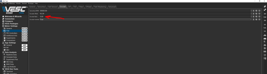
Here are the current FOC-->Encoder settings. It looks like only Encoder Ratio changed. It was 4 from Luna and it did not work. After executing Encoder detection through the VESC Tool menu the VESC Tool set it to 5 and now it works

1760426061112.png
 
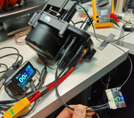
More great news! I figured out how to make the VESC Express work with the Luna M600 controller!

It it turned out all I needed to do is set the VESC Express dongle Baud Rate to 250K.

I can not believe Marcos refused to tell me such simple little thing. Those VESC guys are such petty folk it is unbelievable!

Anyway, we finally made it works guys! So we do not need the USB and the integrated Bluetooth on the PCB anymore!


In order to make to make the VESC Express dongle works you have to make a cable to connect CANH, CANL, +5V and GND pins from a motor case connector to VESC Express dongle (you can use the purple connector in the motor case because it is used for brakes and shift sensor and it is quite useless feature so you can occupy that connector with VESC Express dongle).

You will need this plug (the purple 6 pin Female)


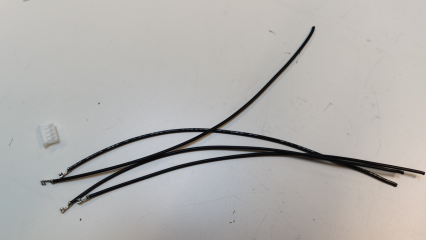
You will also need 2 of JST jumper wires part number ASPHSPH24K305


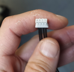
You will also need 1 of JST connector housing part nubmer PHR-4


Cut the JST jumper wires on 2 pieces each and assemble them ito the JST plug

1760430856827.png

1760430895718.png


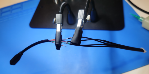
Strip the purple 6 pins plug connector wires and solder them to thee JST plug wires making sure when you connect JST plug to the VESC Esxpress and the 6 pins urple plug to the motor housing connector CANH, CANL, +5V and GND are maching

1760431216752.png

1760430991193.png

1760431243456.png

1760431263408.png


Connect the VESC Express to the motor and to computer with USB cable (you also can use Makerbase VESC EXPRESS, it is cheaper and has Bluetooth in addition to USB and WiFi and also it can take power from USB. So it is basically way better than VESC Express).


1760431459227.png


Open the VESC Tool application and connect the VESC Express. Click "VESC Express", set baud rate to 250K, click "Write" in the bottom menu, click "Scan CAN"


1760428889557.png

And there you have it! Now you can work with the controller and have nice external USB, WiFi and Bluetooth connection!

1760429320447.png

1760432775773.png


I already found a good spot for the integrated Bluetooth module but I guess we do not need this mess anymore

1760433078622.png

By the way, the new Bafang displays have integrated Bluetooth, so if someone knows how to firmware we can make Bafang display Bluetooth works with the VESC through CANbus. That would be the ultimate solution.
 
Last edited:
OK guys, we have some real problems. It looks like the torque sensor from Bafang M560RS (and probably regular M560 torque sensor) does not work with Luna M600 controller.

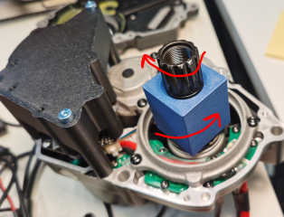
I 3D printed an adapter to apply torque and rotate the torque sensor shaft at the same time and it did not spin the motor. I tried all combinations of torque direction and rotation direction and nothing works. I also tried to calibrate the torque sensor through the Luna interface in the VESC Tool application and it did not work too.

Is there any way to make the PAS/Torque sensor works with VESC Tool?

1760658380493.png

1760658602235.png

1760658629857.png

1760658665159.png
 
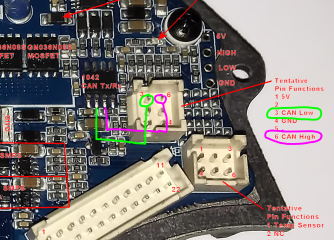
It looks like the torque sensor on Bafang M560RS is not connected to CAN transceiver chip while M600 torque sensor is connected to CAN transceiver chip. We need to figure out if M600, M560 and M560RS are different torque sensors generate different signals and require different connection. I already can tell for sure M600 and M560RS torque sensors are not compatible. Now we need to figure out if M600 and M560 (not RS) torque sensors are different or not.

If anyone has regular M560 (not RS) controller laying around can you please check continuity with multimeter between these pins (those pins are CANL and CANH and M560RS controller has no continuity between those pins on the torque sensor connector and on the can transceiver chip).

1760664846054.png

1760664080555.png
 
Last edited:
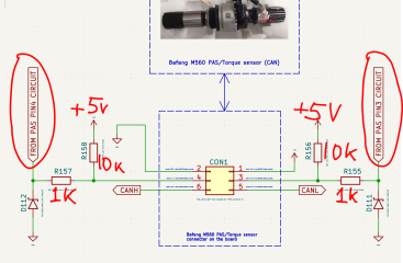
I checked the connection to MCU and It might be the M560RS torque sensor works similar to Bafang M620 UART torque sensor. Two pins are connected through some resistors circuits and look somewhat close to Innotrace controller circuits (not exactly similar thought. It looks like those pins are LJ pin (Torque) and DS pin (Rotation/Direction) just like on Bafang M620 UART Torque sensor,


1760668634838.png

It looks like there are at least two versions of M600/M500 torque sensors with different pinout, CANbus and Not CANbus and Luna designed it for CANbus version. The Bafang M560RS torque sensor looks somewhat close to Not CANbus version.

1760671606991.png

I am not sure if this picture below is M600 or M560 controller but the pinouts of the torque sensor is close to Bafang M620 UART.

1760672861022.png
 
Last edited:
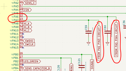
Is there any way to tell how the Luna M600 firmware uses the signals from the pins 22 and 23 of the MCU looking on that VESC page on the Github?


Those pins are connected to the torque sensor through some resistors and 5V circuits (maybe the torque sensor changes resistance between those pins and ground so it works like voltage dividers and the firmware process it like torque and cadence values depending on the voltage?). And how the Luna M600 firmware uses CANH and CANL signals from the torque sensor?

1760676714698.png

1760677048566.png
 
Last edited:
the signals from the pins 22 and 23
PA6 and PA7 are the Quadrature PAS input pins. You can get the crank rotation direction and the candence from them.

But the function hw_get_PAS_torque does not use it, it just calls the function luna_canbus_get_PAS_torque , that returns luna_settings.torque_sensor_output that is extracted from the CAN bus message. The cadence, that is also included in the CAN message, seems not to be used by the Luna firmware, why ever.
The candence is still read from the PAS pins PA6 and PA7.

No idea, why Marcos mixes the CAN information with the "analog/digital" information. 🤷‍♂️
 
Last edited:
Status
Not open for further replies.
Back
Top