We'll need a fair bit more information to help you out, so there are questions below. When answering, keep in mind that more detail is better, and more likely to help us help you.
")
Hi, can someone help me wire this up please.
Just to make sure: What exactly is your goal? What specifically do you need to be wired up, and what functions do you need it to have when complete?
My old system was like this:
Is the "old system" a different bike, or was it a previous set of equipment on this one?
What exactly did the old system consist of?
Do you have a complete wiring diagram of the old system? That would help tremendously in wiring up the new one.
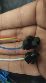
- In the first photo the yellow and red cables are for the physical key.
Where did they connect in the original system?
Where the key is wired depends on exactly what it needs to do for you. Most often it is wired between the controller's lock / KSI / keyswitch / ignition / etc wie and the battery positive, when the controller has such a function that runs on that voltage.
Without the manual's definitions of each of the things in the wiring diagram, I would guess that in your case the keyswitch would connect one wire to each of the "Anti-theft" pins on the controller.
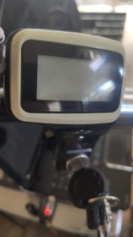
White and blue for the screen.
What specifically does the screen do in your system? Is it just an information display (if so, what information)?
Or is it a display that lets you change setttings in the controller, etc?
Did this display come with the controller you are hooking it up to? Or is it from a different one? If so, which one? (displays are not generally intercompatible with different controllers, depending on exactly what the display is and does).
If the screen only have white and blue, nothing else, then it seems unlikely to work if it is anything like other displays; most have at least four wires, some several more. Is it getting power or other inputs from other wires that are already connected elsewhere?
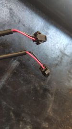
-In the second photo: Red was the + of the battery, blue and green for each directional. I think the black went to GND, but when measuring the voltage it gave a lower value and when the brake was pressed a higher voltage, so the brake light was always on and when the scooter was braked it would light up even more.
Well, the black couldn't go to ground if it gave any voltages at all. That's what ground is for, is a reference to be 0V to "compare" the voltages to.
Brake lights can be wired in a few ways, some of them use a common ground and some use a common positive. The switches might be wired between any of the lights and ground or positive depending on the brake lights themselves, and the rest of the system wiring.
What did the red wire connect to on the old system?
What did the black wire connect to on the old system?
-All my lights run on 60v.
Is your present battery a 60v battery? If not, you'll need a DC-DC converter to provide the 60v the lights use, out of whatever your battery voltage is.
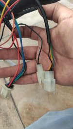
- Finally, in the third photo are the cables of each brake.
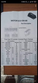
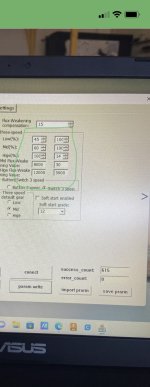
-I also attach the screen model and the wiring diagram that my model has.
I didn't see a wiring diagram for the screen, or a screen model, just a controller diagram and model. There is a picture of a display with a keyswitch below it, but that's all.
I really don't know how to connect any of these cables or the necessary settings in the software.
Which settings are you referring to?
Are these in the controller, using computer-based setup software? (or an app)? Which version of software (or app) are you using, and how is it being connected to the controller?
If you mean for lighting controls, the controller does not generally operate any lighting; that is usually done with external switches or relays.
If you mean for motor settings, that depends on your specific motor and whatever the controller's manual says to use for it, and your specific usage and conditions. (because you need to make sure the controller is set to not allow more power than the motor can handle, but still enough to do the job you need the bike to do).
If you mean for your battery settings, that depends on your specific battery, the controller's manual, and your specific usage and conditions (because you need to make sure the controller is set to not use more current than the battery can deliver, or go too low in voltage).