• Hello ES! We could use some help to get us past the finish line on building the new knowledgebase for the forum.
    Can you donate? Please see our fundraising page. Thank you!

Luna M600 Ludicrous V2 reverse engineering and firmware making

I checked and my flipsky mini also has a shunt on the low side it is compatible with Vesc 6.6
Yes, shunts on the low side of the power stage circuit of the controller is OK, but I am worried about the swapped Kelvin connections polarity of the shunts sensors to the current amplifier on the Luna controller except this thing can tolerate bidirectional mode and Luna did not mess things up. I am talking about low side and high side of the shunts and not low side and high side of the whole power stage circuit of the controller where the shunts are located.

You probably will not be able to check the polarity of the Kelvin connections between the current amplifier and the shunt without unsoldering the shunt and looking to the current amplifier chip datasheet, but if you have an exposed controller laying around you might be able to confirm using a multi-meter - for the low side current sensing configuration one Kelvin trace from the shunt will ring to the ground with unsoldered current sensor resistor (that is low side) and other Kelvin trace will not ring to the ground with unsoldered current sensor resistor (that is high side) and you can confirm where the low side and high side are connected to the current amplifier and check the current sensor amplifier datasheet for pinout and see where "IN-" and "IN+" pins are connected (which one to low side and which one to high side).

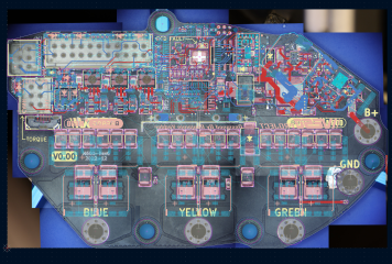
If you have an exact controller like on the picture it looks like the current amplifiers are right at the shunts and so you might be able to confirm polarity and low and high sides of the shunts just visually without undersoldering and ringing.
 
Last edited:
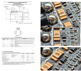
Yeah, it is hard to tell looking on the picture where the tracks go and where the low side of the stunts. Luna has the same bidirectional current amplifier (just combined 4 in one chip) as the one you posted.
 
In my opinion, if the current sensor amplifier is bidirectional, it's possible to connect it incorrectly according to the datasheet. You just need to include the correct "reverse" current direction in the software, which the microcontroller will read. I think Luna connected it incorrectly because their connections were crossed, and that was the problem.
 
The connections crossing or wrong polarity could be avoided simply swapping the "up" and "down" pieces of tracks from the Kelvin vias at the shunts. And Luna did intentionally swap the tracks pattern at the vias on the B shunts (it does not match A and C low sides shunts pattern and it was necessary to keep "wrong" polarity connections and to avoid crossing of the tracks). I guess I will just copy what Luna did and let's hope they knew what they were doing.

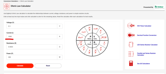
We can calculate and estimate if such connection can work. There are 2 current sense resistors 0.0005 Ohm each connected parallel, therefore the resistance of the circuit is 0.0003 Ohms

1752852637175.png

The maximum voltage this current sense amplifier can tolerate on reversed polarity in common mode is -0.3V. Therefore up to 1000A can flow through each phase before the magic smoke on the current sensor chip will appear

1752852946937.png
 
Last edited:
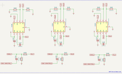
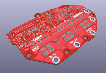
We did it, guys! The schematic of the VESC for Bafang M600 controller is complete! Thanks to everyone who participated in this colossal effort!

Feel free to download this milestone KiCAD files, review and comment!


There are few circuits drafted inside red rectangular areas we still need to figure the purpose of. This is a little puzzle for you guys, feel free to guess what those circuits do.

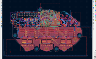
Now the fun part - finishing the PCB tracing!

1753059250715.png

1753059383784.png

1753059433486.png

1753059519048.png

1753059549262.png

1753059602235.png

The Power stage and last STM32 connections

1753059677110.png

1753059733430.png

1753059920090.png
 
Last edited:
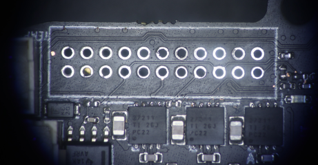
Cleaned the conformal coating residue and took good pictures of the places under the STM32 and the main harness connector. The next step is to transform the images to align with the actual geometry to have good reference

1753239189679.png


1753239317968.png
 
The rotary magnet sensor circuits have been reverse engineered!

So is running over SPI?
I have noticed this chip can be configured to any output (but documentation just on a request - weird).

Just a thought, if somebody can confirm. If configured to ABZ output. After powering on VESC, very first start needs to blindly rotate up to one revolution to find zero, right? Wouldn't be there issues with first start?

I have noticed with my Innotrance M620 controller, it is not starting sometimes and hang with that funny sound (like belt slipping). Does it mean Innotrance is going sensorless, or is it some fault in starts over halls? It is shame it has this fault. I need to press sometimes throttle many times to start. Is possible to fix this? Have bought the VESC Tool software now.

Good job Tpehak! Just it is too complicated for average skilled DYI person. :( And to make it work properly will be pain and lot of time and testing.
 
So is running over SPI?
I have noticed this chip can be configured to any output (but documentation just on a request - weird).

Just a thought, if somebody can confirm. If configured to ABZ output. After powering on VESC, very first start needs to blindly rotate up to one revolution to find zero, right? Wouldn't be there issues with first start?

I have noticed with my Innotrance M620 controller, it is not starting sometimes and hang with that funny sound (like belt slipping). Does it mean Innotrance is going sensorless, or is it some fault in starts over halls? It is shame it has this fault. I need to press sometimes throttle many times to start. Is possible to fix this? Have bought the VESC Tool software now.

Good job Tpehak! Just it is too complicated for average skilled DYI person. :( And to make it work properly will be pain and lot of time and testing.

That's what it does according to the datasheet


1753280316664.png

With Innotrace controller not starting sometimes could be multiple issues including issues with torque sensor (I had a bad torque sensor and that sensor caused not smooth power output and not consistent initial pressure on the pedals to start the motor working and some other glitches. Replacing the torque sensor solver it). It also could be damaged rotary encoder (it can be damaged by the rotor shaft if the shaft got loose and hit it, most likely cracking the chip legs so the rotary encoder lost contact or the contact becomes intermittent. I made a 3D printed bumper to protect it and also replaced the rotor and the second gear for new version with more teeth and lesser helical gear teeth angle which hopefully will reduce the lateral force and the chance the shaft will get loose and start hitting the rotary encoder again).


Last edited:
That's what it does according to the datasheet


View attachment 373942

With Innotrace controller not starting sometimes could be multiple issues including issues with torque sensor (I had a bad torque sensor and that sensor caused not smooth power output and not consistent initial pressure on the pedals to start the motor working and some other glitches. Replacing the torque sensor solver it). It also could be damaged rotary encoder (it can be damaged by the rotor shaft if the shaft got loose and hit it, most likely cracking the chip legs so the rotary encoder lost contact or the contact becomes intermittent. I made a 3D printed bumper to protect it and also replaced the rotor and the second gear for new version with more teeth and lesser helical gear teeth angle which hopefully will reduce the lateral force and the chance the shaft will get loose and start hitting the rotary encoder again).


Can be also configured to ABZ or UVW. SPI is the best. I can not even find in documentation in which output is coming this chip from factory.
 
As I understand the chip has all 3 modes and it choose one depending on the electrical connections.
 
There is one time programming procedure and you need to choose which output u want, with some calibration params, zero position and so. Programming voltage is 7V.

I guess it comes in SPI.
 
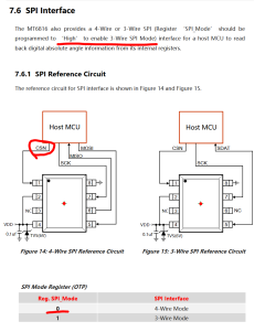
It looks like as long as CSN signal presented the chip transfers data in SPI mode. The only programmable thing is if you want to make it works in 3-Wire SPI mode instead of 4-Wire SPI mode (the default SPI mode is 4-Wire). The register SPI_Mode can have only 2 conditions, 0 or 1. SPI Mode always exists and you trigger this mode by using the CSN pin. If that pin is not connected the chip works in other modes.

1753294988631.png
 
Last edited:
Yes, when the chip does not receive signal on CSN pin (PIN#1) it works in other modes. It looks like the only requirement to make this chip to start working in SPI mode is to send signal on the pin#1. Well, maybe also send voltage on the PIN #2 below 7V (which is what Luna controller also does)

1753295660548.png
 
Last edited:
Yeah, you enable SPI mode sending VDD below 7V (below 6V actually looking on the TVS diode and below 5V looking on the VDD maximum voltage) to the pin #2

1753296451876.png

1753296571924.png
 
No worries. That ABZ and UVW sensing was just my curiosity. In the beginning thought this chip is just SPI. I am still stucked at rotary sensor, need to catch up, but u are fast. ;)

Whats your next plans? Will you try to build your board?

That BT is nice and tiny. And integrated antenna also. But also can not find it on internet.
 
Last edited:
The next step is to finish the tracing and assemble the original board back and see if it works at all. Then, if it works we can build the reversed one to confirm if it was reversed correctly.

The Bluetooth requires external antenna though, there is a connector on the board. If you click on the part designator on the board picture area in the schematic in KiCAD it will open the link to where you can purchase the part. There are also links for each part in the "Symbol fields table" or in the Symbol properties.
 
Last edited:
The power stage is complete. There is only internal some layers left and we can get ready to rumble!

1753511031820.png

1753511070098.png

1753511209999.png

1753511427584.png

1753511501032.png
 
Intersting work! Do you plan on doing the m560 too ? That motor is also quite popular and deserves a vesc controller... Maybe your controller could fit with only changes in the overall shape ?
 
Last edited:
I am planning to reverse engineer only what I have. As I understand the M560 and M600 are about the same and the main difference is M600 has removable controller cover and M560 has no cintroller cover and the motor casing is solid piece of aluminum and the controller can be removed only by opening the motor case. You might be able to use Luna controller on M560 if you can figure out how to mount the controller in the motor case and how to align the rotary encoder with the motor rotor axle.

If you can find M560 CAD model I can take a look and check if it is possible to make Luna controller works with it without significant changes.
 
Back
Top