2WD Semi-Recumbent Recycled-Parts Cargo eBike: "CrazyBike2"

I got the tire changed:
DSC05027.JPG
but it took so long and earned me so many little hurts that I am gonna have to do the spoke stuff on the rear tomorrow after work. Hopefully the tire won't rub a hole in itself on the frame before then.

Four 12V 17Ah SLA under the center of the bike are apparently just enough to hold the front end off the ground a bit, for changing the tire.
View attachment 1
 
Replacement tire performed pretty well on today's commute, though I'm not sure exactly what PSI it's at--the valve must be clogged, because while I can add air, I can't let any out, which the air pressure tester requires.

I did find that the rear tire was only about 20 PSI last night, so aired it up a lot, to about 60. Havne't rechecked it today to see if it has a leak, need to do that hwen I'm not dozing while typing and doing stuff. Probably tonight when I fix th spoekes.


The front tire definitely feels different. I think it is a bit larger diameter overall, but I'd have to measure that. It feels like it steers a teeny bit different, and i know it's not smaller diameter, so larger would probably account for hte steering differences.

More later when I'm mor eawake.
 
I can't remember what I was going to post more about up above. :(

I've managed to misplace my freewheel removal tool and wrench, again. So still haven't fixed the broken spoke, but really need to before it leads to more of them snapping.

After getting frustrated with looking for the tool, after nearly 2 hours of wasted time, I gave up and started working on the disc brake rotor idea from here:
http://www.endless-sphere.com/forums/viewtopic.php?p=409601#p409601
http://www.endless-sphere.com/forums/viewtopic.php?f=2&t=28410
which I'd drawn up on a steel plate here:
http://www.endless-sphere.com/forums/viewtopic.php?p=473435#p473435
but was waiting for hopefully some input before I just went ahead with it. Or more hopefully, fidning an actual rotor I could cut down to use. Seeing as neither happened, I decided I might as well start on it.
View attachment 4

I got it cut out without warping it, and managed a pretty bad but usable fit to the hub cover, with about 2mm "slop" on the inside hole after rounding it out and removing sharp edges. Then I took the flapdisk to it to take the paint/coating off of it.
DSC05067.JPG

I still have to drill the holes in it to bolt it to the hub, and then I can seal up the holes in the hub cover so I can then just use the grinder on it with the wheel in the air, running the motor, to both trim the outer circumference to a real circle, and to finish the braking surface with a sanding block.
View attachment 3

I have no plans to drill holes in it yet, but I will probably have to do so to improve braking/cooling with it.

I also will probably wind up having to cut sections out between the bolt points, to fix heat-swelling/curving problems causing rotor/pad friction when not braking, but I will wait until it is necessary before I do that. I'd much rather just bolt the thing on, weld some caliper mounts to the fork, and start using it for braking. :)

The finishing of the surface will include thinning it up some, because it's almost twice as thick as a typical bicycle disc-brake rotor, and it is not going to fit in there with any clearance to the pads.
DSC05071.JPG

In this pic, I stuck a mechanical caliper on there I'd gotten from AussieJester, and it will hang on even upside down. :(


I'll probably put calipers on both front and back of the fork leg, so that I can have more braking power. I have a dual-lever from AussieJester that can be adjusted separately for each one, so I'll use that to control them, and fine-tune the braking with them.
DSC05070.JPG

I'll also leave the rim brakes, cuz my wacky contraptions don't always work as planned. :lol:
 
Ok, I don't like this Kenda front tire much on here; I can skid it too easy, especially applying a burst of power, and I can even cause it to lose traction in a turn by doing that. :( Since I routinely coast just up to a turn, sometimes braking just before it if I am going to fast to make it with out scraping the cargo pods, and then accelerating into the turn itself, this is a problem.

Also, I can EASILY break traction on it going to full throttle while sitting at a stop, and if I simply keep my feet on the ground and push just a *little* bit, it'll never grab, unlike the Cheng Shin I had on there before (that tore open), that would slip a teeny bit first and then grab, unless I actively pushed hard with my feet.

Not sure what to do about it yet, but my best option for a short while would be to put the other (well-worn) Cheng Shin on there instead--it was the mate to the first one that's torn.

I've got a couple other tires, too, including a similar but not identical Kenda off an old Landrider. Don't like it for the front because it's edges are less round and more knobby than this version. Also a Kenda Kross that has flat center but really knobby edges, practically a rectangular cross section because of that. Don't like that in front.


In other news, another donation box arrived, from Texaspyro. Hachi is a bit frustrated, because it doesnt' smell like it has any goodies, and she's wondering when people will start sending HER some donation boxes with nummies in them. ;)
DSC05040.JPG

Bunch of interesting and useful stuff:
DSC05043.JPG
An old BJ-10e portable inkjet and Palm m5xx series PDA, which might be able to run Veloace (not sure, have to try to sync it and see). Haven't tried either one yet.

A Fluke DMM, old pushbutton style, and a couple mini-DMMs that I don't know the brand of. I think the battereis in all of them are dead; easy to fix, gotta check. I like the little mini-meters; once I find out what's wrong with them and fix them (batteries?) one of them is going in the on-bike tool kit. The Fluke is nice: I have not used one like that since I worked at Honeywell, where we had the LED-display version of it that was in a hardback-book-sized case, with the pushbuttons on the front under the display. I'm sure what we had was older than this one; it was certainly less portable. I've not tested why it doesn't turn on but i expect it's a battery.

An HP flimstrip/slide scanner adapter, exactly like the one I started out with on DayGlo Avenger for it's headlight. :)

A small slew of LED-based lamps, four MR16s, intended for 12VAC or 9.5VDC; some PAR20 and PAR30, screw base for 110VAC. Also a "dead" unit that's already partially disassembled. More on these in the next post. :)

Pair of Harbor Freight LED flashlights; these are useful; wanted a pair for low-level lighting of the bike at the front fork, axle-height, now I have them. Have to wire them up to main power, though, so probably series them to run off the main lighting pack, along with a third one I have around herer someplace, put up above the front tire, so they'll total take about 13.5V to run. (4.5V each, three AAA normally). Or just make a constant-current source and use just the two.


Somethign that will probably get it's own thread once I have time to start working on it is the set of cables and such on teh right--it's a good portion of a CD tab welder--pretty much everything except the electrodes, from what I can see. :)
 
I did a little experimenting with the already partly-disassembled LED bulb, as well as a second larger/higher power one that was marked "bad" that didn't light up when screwed into a lamp (all the others do).

First, I disassembled the smaller one the rest of the way, just to see what's in there. Not like I'm going to hurt it much. ;) First up was detaching the LED from the stuff inside, so I could see if the LED could be removed, and also to see if it even worked. I chose to cut the red and black wires to it, leaving just enough to clip test leads to.
View attachment 25

Then I promptly forgot that I was going to test the LED (with the small Sorenson), since I'm easily distracted, though this time I don't remember by what. I got the vise-grips out, and twisted the base away from the heatsink/LED module, and it popped right out, leaving some brittle but flexible silicone potting behind, and exposing part of the internal PCB.
DSC05046.JPG

Interestingly, I was able to push the whole silicone plug, PCB and all, right out the end of the plastic cylinder base with my thumb.
DSC05047.JPG

Breaking off the silicone was fairly easy, done by hand, but I slipped and broke this inductor off. I'ts marked, so I may be able to find one on another bit of electronics to replace it.
DSC05048.JPG

Hopefully I will, because a meter check finds that the fuse is blown:
DSC05049.JPG
It is likely something else caused it to blow, but I won't know till I rpelace the inductor, and hook it up to a load and power it on.

Anyway, hte PCB isn't necessary to use the LED module, but it might make it easier, since it's essentially an SMPS and will probably work on much less than 110VAC, and probably on DC, like my bike's traction battery pack. (like my CFL taillight does)

So...on to the interesting part: testing the LED itself. I assumed that 3-4V should be needed for each "segment" of the LED, of which there are 3 series rows of what seem like 15 or 16 dies in parallel. Ought to take maybe 9-12V at an unknown current level for full brightness.

At first testing, the LED will emit a bit of light in a dark room at only 6V, but the camera can't pick it up.
DSC05054.JPG

I have to go to 7V to get camera-readable light out of it
DSC05055.JPG

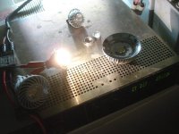
The Sorenson is limited to 100mA current at this point, just so I don't blow anything by accidentally spiking the LED with power. It might not be a regular lamp anymore, but it certainly has possibilities for CrazyBike2 lighting. :lol: This is a pic of it at about 7V or so, with the room lighting on (15W fluorescent)
DSC05053.JPG

Upping to 7.5V gets a LOT brighter:
DSC05052.JPG

but compared to the room lighting it is still barely lit
DSC05051.JPG

On to 8V and up, about a volt increase each pic, having to increase to 200mA in the third pic to get the voltage to keep going up:
DSC05056.JPG

DSC05057.JPG

DSC05058.JPG

By the fourth pic, at about 11V, 200mA or so, it ws so bright the camera had afterimages (which did eventually fade, but I was afraid they might be permanent. I think that ther eis still a bit of shadow in spots I pointed the camera at the LED in, when I point it at a blue section of sky. :( )
DSC05059.JPG

The LED is epoxied to the heatsink, so I risk destroying it trying to remove it. I'll probably just leave it on there and use it as one piece, in whatever I end up putting it in.

The last bit of testing I did was to push the voltage and current up, watchign each carefully, until there was a balance that was around 11V at 600mA or so. Far too bright to look at even at a distance. Gets toasty hot (can't put finger on actula LED unit, though theatsink was still just getting warm).


I also disassembled the "bad" large bulb, which has an even more powerful LED. It turns out to have about 10 series sets of what seem to be 10 dies, but might be more--they're so small I have a hard time seeing them, and you cant' tell the difference between their edges when they are lit up at all.

Popping off the lens assembly was easy, but I pushed too hard at the wrong moment and cracked an edge off. Most of the "reflector" is actually just the cone of plastic, all clear, using the same reflective properties that make fiber optics work--different densities of material with different optical properties, so light reflects within the denser material, letting a lot less of it out the "sides" than reflecting forward.
View attachment 11

THe white "basket" that holds the lens also secures the LED to the heatsink, as unlike the previoius one, isn't epoxied down.
DSC05075.JPG

This one has nothing but the pressure of that basket holding it on, and white regular heatsink paste (the stuff that alwasy dries out, usually quickly), helping it contact the heatsink. No polishing on heatsink, either--its actually painted this dull gray like the outside, which probably does not help get heat away from the LED. Perhaps that is why the bulb died--the LED pulled more current than it should because it was too hot, and overloaded the PCB.
DSC05077.JPG


The two screws also hold down the base plug, so after cutting the LED supply wires, it was easy to remove.
DSC05078.JPG

I dug into the brittle but squishy silicone, carefully, and excavated as far as I could without risk to components. I still couldn't push the PCB out like I did with the previous one.
DSC05079.JPG

DSC05080.JPG

So I had to cut the shell off the potted PCB.
DSC05084.JPG

View attachment 4


Then I was able to remove the potting silicone, pretty easily:
DSC05086.JPG

The fuse, far right in this pic, is intact. But the inductor on the top right is damaged from my cutting the case open. :roll:
View attachment 2

Not much damage, just one light scrape thru it's heatshrink, but I must've cut a wire in it becaues it reads open. :(
DSC05088.JPG


The LED chip itself, well, that's pretty thin, metallc substrate with ceramic coating, I think, then the LEDs on top under a silicone covering and phosphors. Chip area about the isze of my pinky nail, unit about the size of my thumb's fingerprint.
DSC05089.JPG

I didn't take pics of the ligthing experiments, but it takes about 30V to light up at all, and at 42V or so it draws about 500mA, and is far too bright to look at, and gets pretty warm. I am sur eI could push it further, but that was enough to let me know it's very usable.

I'm considering putting one of those modules into my taillight, in place of the CFL. Probably use the second one as a brake light in there. I dunno how many lumens each puts out, as I haven't run across my light meter in quite a while.
 
That big bulb was around 15W... it just died when I flipped the light on. Out of the 200+ LED bulbs that I have installed, that was the only bulb that died in use. Usually I had to replace a bulb or two every week. The smaller/disassembled one arrived DOA.

Those LED arrays REQUIRE heatsinking... for open air passive heatsinking they recommend 10 square inches of surface area per watt. A little fan power greatly reduces the needed heatsink size. A case temp of 70C is well within the LED tolerance. I think that those are BridgeLux arrays... they can run at 105C case temp, but lifetime specs are guaranteed at 70C. The heatsink on the MR16's runs around 63C.

Without optics, the beam is around 110 degrees.

The MR16 LEDs are 250 lumens. The PAR20's are 350 lumen/25 degree. The PAR30's were 700 lumen(?) 15 degree spot. The PAR38 was either 800 lumen/25 or 40 degree
 
For welder electodes, 4 ga copper ground wire works well.

For hand held electrode holders, I take two of those terminal lugs and bolt them together at a 90 degree angle. One terminal goes onto the cable and the other holds the electrode.

And for an SCR welder, put a beeper across the welder electrode connections. That way it will beep if you blow out the weld or remove the electrodes before the cap is fully drained (which means the SCR didn't turn off).
 
Thanks! That helps lots more than you might know. :)

I took a look at the LED from the big one, and it doens't have any markings at all, back, front or edges, printed or engraved, other than a + and - at the terminals. It doesn't quite match the Bridgelux spec sheets for plate design, but it's really close to one of them. Might be a custom version just for Sylvania, but more likely it's some other brand; I don't know for sure.


I spent a minute checking the Cree P7 from Methods, using hte Sorenson, and I got up to 500mA at 3.2V before I stopped, whcih is not even half of it's power level (but I don't have it heatsinked yet). It was already brighter than any of the others. So this one will end up as headlight (especially since it already has a reflector, though optics would probably help make a better beam; I have yet to test it's beam ability).

So..maybe use the big flat LED for taillight, and modulate the current to it for say, half current taillight, full current brakelight. Not sure yet. I think first I need to work on the actual brake before I worry about signalling about it. :lol:
 
I would not put much current through these power LEDs without heatsink. They are easy to damage.

The P7 should not be nearly as bright as these larger LEDs, and P7's take 2.8 amps as I recall. Not sure what you have but an SST-90 requires 9 amps full current, and you have some LEDs there larger than SST-90s. They are much higher voltage and total power.

A power LED at full power with no heatsink will be destroyed in a couple of seconds or less. So you are a ways from full power on these.
 
Ah, ok. The bag the P7 was in was marked Cree P7 1000 Lumen 1Amp, so I made an assumption ;) that that was it's rated spec. Might instead be the limit of the little board that was in there, instead. I'll have to look it up (tried to find it on Cree's site, but I got confused by all the different types, as I didnt' know which one of many the P7 is. I'll just have to look thru all the datasheets here: http://www.cree.com/products/ledlamps.asp and figure out which one it is).

I had the unheatsinked large flat LED in my fingers, so that I could yank the power off quickly if I felt it getting more than a tad warm. The other small LED is epoxied to it's heatsink, and even so it got quite warm (not hot, but uncomfortably warm).


Now for more pictures.

First, on the MR16 bulbs, the optics are very easy to remove, only held on by an aluminum ring pressfit into place:
DSC05060.JPG
Clear cone does same thing as in the larger units. Mibht be possible to polish teh face of it to help it focus instead of scatter light.

Tested out on the Sorenson first, they're certainly bright enough.
DSC05097.JPG

Night before last, I had trouble sleeping as usual, but also as usual wasnt' really doing the thinking things really well, so decided to try something relatively safe--swapping out the incandescents in my turn signals for the MR16 LED units.
View attachment 9

They're more directional, but significantly brighter:
DSC05091.JPG

Still easily seen from the sides, though, which is part of what I want:
DSC05092.JPG

DSC05099.JPG

At the rear, as high up as they are, pointed straight back, they're VERY bright. Probably 3-4 times brighter than my CFL taillight that is powered on in this pic:
DSC05093.JPG

Without the flash on, normally lit room, brake light bar, CFL taillight, and LED turn signal on. It's so bright in total that the camera stepped down enough to not pick up most light out side those, including the white light shining down and forwards from the taillight's "license plate" light.
DSC05098.JPG

I used two differnet ways of hooking htem up, because at first I wasnt' thinking well, and was sure I'd have to disasemble them to get to the internal wires, since soldering to the pins would probably melt the casing, if it would work at all (they're steel).

I didn't think to take pics of any of this, so I went back and took at least some pics today, of the light inside hte signal case, after the text below:

At first, I thought I'd open one up since the base is screwed to the heatsink, and found soft gooey silicone covering the PCB, with wires actually crimped to eyelets that slip over a threaded post that's the inside end of the MR16 contact spikes, held down with tiny nuts.

I undid the nuts, and connected the eyelets to the signal wire and backplate, stuffed some padding aroudn the MR16 housing to keep it from bounsing around, and some electrical tape around the PCB to ensure it doesnt' short on the reflector or the bulb positive, and closed up the housing. DId the same for both front lights.

For the ones in the back, I was too tired to undo the screws, and had a flash of momentary thought. I cut some 14g (maybe 16? not sure) wire off some old harness stuff, and twisted the still-unstripped end over teh very pointy pins on the MR16 base, so taht the pins were enclosed in the issulation and making good contact with the wires. Stripped the other ends, and connected thse to the signal and ground inside the housing.


Taped over the whole pins end to prevent shorts against reflector/etc in the housing, and pushed the end down into the former bulb-base recess. I was going to use foam to cushion the LED bulbs, but didnt' remember where it was, and wanted to finish and get to sleep, so I just used some junkmail, temporarily:
DSC05094.JPG

Then I took a cell out of the lighting pack, which is a 4-cell lipo-type experimental pack (now 3-cell). I figure it ought to be ok for short blinks at the higher voltage, but didn't want to risk it at essentially double the voltage it was meant for. :lol:
DSC05095.JPG

DSC05096.JPG

I still have to build a new blinker, since the old '85 Honda blinker died earlier this summer. Since it doesn't ahve to handle high currents, I can make it simpler now, so it's more likely I'll get around to it soon. Until then I just keep blinkign the manually.
 

Attachments

  • DSC05063.JPG
    DSC05063.JPG
    39.4 KB · Views: 4,502
I've run those MR16 bulbs on 4S A123 packs without any problem... as usual, YMMV. I've also run them at 15VDC. The peak voltage of a 12VAC is around 17V. I suspect they would work fine around there.
 
I did some more checking. Turn on is around 7V. Below 10VDC they draw 8W (rated power) At 12V they are drawing 9W. At 13V 9.35W. At 14V they suck 9.8W So the switcher is losing steam above 10V.
 
As long as they arent' likely to get too hot in a 50/50 1/2sec cyclic use like turn signals, totally enclosed inside plastic housings, I'd ideally like to be able to run them up to the 16.4V hot that my lighting pack was at with 4 cells. They seem to be fine at 12.3V this way, even if I leave them on for a couple of minutes (like during my photos above).

Later, once I work out an LED headlight, I wont' need the higher voltage to drive the incandescent headlight sufficiently, and I can run them closer to a sane voltage. :)
 
I left one on for 12 hours or so at 14V. It got nasty hot, but sill worked. It was sitting on a piece of thermal cash register receipt... that turned black.

The tree guy showed up today to work on some trees... he has some nice, long ladders and swapped out the remaining PAR20 halogen bulbs under my second story eves with LED bulbs. I also replaced the six 18" Lumiline incandescent bulbs (which are no longer made and new sell for up to $200 each!) in my dining room table with some LED replacements that I made from 10 meters of LED strip lights stuck to dowel rods. The only incandescent bulbs that I have left are in the fridge and microwaves.
 
Might be worth sticking all your old bulbs in a safe for a few years, then selling them off to pay off all your debts. :lol:
 
amberwolf said:
Might be worth sticking all your old bulbs in a safe for a few years, then selling them off to pay off all your debts. :lol:


I don't think our pyro friend has much debt concern. :)
 
That might be true. But still.... :)


Regarding the MR16s, I am thinking at this point that I'll just keep it at 3 cells (12.3V) until I get the LED headlight optics and current supply worked out, and probably end up with a DC-DC converter instead of a separate lighting pack, because I won't need the high current, then.

I'm also probably going to put some sort of dimmer switch on the lights. Possibly automatic, with a manual override, so that when it's brighter than some set level for ambient light, they brighten up to maximum, for better daylight viewing. But then they dim below some threshold, to keep from blinding people at night. :lol: These things are REALLY bright, compared to the incandescents, especially within that primary cone of light, even though it's almost all just the amber light that gets thru, and a significant amount is scattered by the covers.

If I want to see stuff in the direction I'm turning, I can just stop the blinking of the turn signal, and leave it on solid. Since the front ones are angled out to the sides nearly 45 degrees, it works very well. :lol:

I'm probably also going to paint the heatsink fins on the face of it white, so they scatter the light more diffusely to the sides for better side visibility of the signals.
 
liveforphysics said:
I don't think our pyro friend has much debt concern. :)

I'm a firm believer in "if you can't pay for it, you can't afford it." Never borrowed a penny in my life. Never had a credit card either. If you're not on this path... daveramsey.com is a good place to start.
 
I had to learn that the hard way, unfortunately. I certainly believe in it now, but I'm in the situation I am in now partly because I did not when I was half the age I am now.
 
Some more ride videos in the process of posting over in the ride vid thread. http://www.endless-sphere.com/forums/viewtopic.php?p=480321#p480321
a pic of the bike, freshly loaded with groceries filling both pods *and* the leftside battery box (whcih is currently empty).
file.php


Yesterday, I also hauled home a couple big bags of dog food, one in each pod (putting all my regular stuff for work and ride in the empty left batterybox):
DSC05139.JPG

A friend and I used his truck to move some stuff my bike can't yet: a couple of very old hospital beds.
DSC05143.JPG

One electric,
View attachment 6


whcih works and can raise, lower, and tilt the head and foot independently
DSC05152.JPG


one hand-cranked, which can't raise or lower but does tilt head and foot separately.
DSC05150.JPG


No mattresses included, but tha'ts ok, becaues the one on my "bed" right now (what's left of an old waterbed frame, using a regular spring matrss on it now) is the right size to fit on there. I just have to strap it down so it'll follwo the folding of the frame. Always wished I had one of these, especially after the waterbed failed beyond my abilityt ot repair it.

The nursing home (over on 47th Ave & Olive, here in Phoenix/Glendale) has about 60 of them that they need to give away in the next few days. Any that arent' will just be scrapped. So anyone in Phoenix area that needs one, PM me and I'll give you their phone number to set up a pick up time with them. Most of them are the hand-crank style, but a couple more are electric. I'd've gotten more but we could only fit two, and the electrics were too heavy to stack one on the other, so I got one of each.

I'm hoping to be able to get at least more of the side rails, which are aluminum with stainless steel riser tubes that slide within brass bushings, to raise and lower them on the beds.
DSC05145.JPG


These look like very useful cargo racks. Seriously considering using two of them, to fold down to either side of the back of the new bike, for wide loads.
DSC05144.JPG


Also considering using the worm gearing from the handcranked version to be run from a motor to lower actuated "landing gear" on the new bike, like AussieJester's, rather than a kickstand.


One use I would have for an extra electric one is a bike work table. I could take the whole bedframe spring/mesh part off, and build a flat worktable on it, in segments that would fit in the frame itself, with a ramp up to the end of it to roll a bike onto it. Then I could raise and lower the bike about a foot to work on it. If I had more than one of these to work with, I might be able to join the frames in such a way to raise/lower the frame twice as far, whcih would be very useful. IT would be sturdy enough for even a small motorcycle, maybe 300-400lbs. Certainly enough for my ebikes. If I took the wheels off, it'd be about 6-7" closer to the ground, making it that much easier to get the bike onto it. Not sure if ti could be made to go any lower than that, would need to examine the way the riser pistons work on each corner post.


But it would certainly make a number of things easier to do on it, without having to sit on the floor to do it.
 
Back when I was checking out the LEDs, I also did some other work that I forgot to post. First was some possible heatsinks with fans for the LEDs:
DSC05100.JPG

DSC05101.JPG

DSC05102.JPG

DSC05103.JPG


and a couple shots of the AC LED spotlights on various DC voltages:
DSC05065.JPG

DSC05066.JPG


Next was a fix for the brake disc thickness. These calipers come apart to change the pads, so it made it easy to just makea shim to go in there. The shim is bits off the tin they removed from the roof during the reshingling after the hailstorm a year ago.
View attachment 10

View attachment 9

DSC05107.JPG

I got the disc cut out and pretty well trimmed up, though the outer edge could use finishing to a consistent radius. Have to mount it to the motor and spin it while grinding to properly achieve that. (wont' fit on the lathe).

This is kinda what it will look like when mounted on teh bike, though inboard of the fork leg. :) And of course the calipers flipped over the other way.
DSC05108.JPG


The calipers have various inner thicknesses, where some may interfere with the spokes. This series of pics shows a spoke held in place about at the angle and position they are at in the wheel, vs. the calipers sitting on the disc that is bolted to the motor.

View attachment 6

DSC05117.JPG


These just show the rotor bolted to the motor. Note that at least one bolt is loose, because the holes are not yet perfectly matched to the cover holes, *and* the bolts are not long enough.
DSC05118.JPG

DSC05125.JPG

View attachment 2


I have to dig thru my stuff to find some longer bolts that will fit it. I don't know offhand what size these are, just whatever the 9C 2807 uses for cover bolts. I need them to be about 5-6mm longer than they are. This pic shows the bolt held against the cover edge, spaced with the head away from the cover by about the thickness of the disc rotor; it doesnt' leave enough threads to catch and mate properly with the magnet ring's holes.
DSC05130.JPG


Till I find the bolts I can't mount it on hte bike yet.

I do have another bit of work in progress, and that's changing the fork to a stiffer one that will handle the extra stresses of the disc brake without wobbling back and forth like the current crappy one does. It might even have *slightly* better suspension, but not by much. It's the Hill Assault fork I picked up early October last year, at first intending to use it on here, but not being able to because I needed a 1-1/8" headtube, whcih CB2 didn't have at the time.
DSC03484.JPG

It does have it now, added on for the DeathRace when I tried to use a better suspension fork, which turned out to be just a bit too long and caused geometry change that resulted in the death shimmy at speeds somewhere between 15-25mph (I can't remember exactly where it started).

This fork is also a bit longer than the other...BUT: it is a double-crown fork with adjustable-position crowns, and the legs can be moved up or down within them, so I can fix the geometry by pushing them up thru the crowns some, and still get full suspension out of it. :)

I still have to weld disc brake mounts to it. I will probably do that by mounting the other 9c/GM motor, with the disc partly bolted to the covers, in just the bare fork, then clamp the calipers to the rotor, and use that to figure out where to put the disc caliper mounts on the fork. Take the motor out, weld the mounts on, then put the fork on CB2. Maybe by then I'll have the bolts needed to hold the disc on securely, and can do the whole job at once.
 
Here's the motor with disc in the new fork:
DSC05212.JPG

DSC05213.JPG

This is the caliper mount (and dropout) off a destroyed RST Omni fork from a bike that was twisted up and mashed (probably hit by a car).
DSC05207.JPG

It's good hard steel, throws orange sparks, and is nice and thick. But it isnt' wide enough to use directly, so I will have to either weld it to another piece of metal to put it on the fork, or I will have to use it as a template to cut an entirely new one out of the other piece of metal.
View attachment 5

you can see the large gap I have to fill at the bottom end of the mount, due to the angle of the calipers at this diameter. Only the top few mm is touching the fork leg.
DSC05214.JPG

From the top, you can see the mount plate could actually pass all the way to the inside of the fork leg; I will probably end up using some sort of spacer on the disc itself to the motor cover, so that the caliper is closer to the fork leg, and the mount can be welded more thoroughly to the leg (partly thru it)
DSC05215.JPG

Two possibilities for the metal plate source. A chair back support brace, from an old computer chair--very hard. And the alternator mounting bracket from the old (now gone) Ford LTD. I'm not sure there's enough flat metal without holes in it on the alternator bracket, but there is on the computer chair brace.

DSC05216.JPG

DSC05217.JPG

I need to find some more recyclable items with hard metal plate of this thickness, as there are a fair number of things I need to use it for.
 
Still refining the disc brake caliper mount, before I finalize it and weld it on, then swap out forks and install the disc (once I have cover bolts long enough).

In the meantime, it's rainy season (finally!), pouring pretty good last night (my day off) and I figured it might do it again today on my work commute, so I put fenders on CB2, one of them off of my "new" pedal bike
http://www.endless-sphere.com/forums/viewtopic.php?f=2&t=33246
DSC05287.JPG


and one of them off my imitation Dogman-Frankenbike-Longtail:
http://www.endless-sphere.com/forums/viewtopic.php?f=2&t=33291
that is still just pieces and ideas.
DSC05286.JPG

Since the fork doesn't have mounting points for a fender, I just ziptied those to the dropout end, and bolted it to the mounting point on the brake boss bar at the top of the fender curve.
DSC05289.JPG

Doesn't quite fit right, and keeps shifting around, with the fender stays rubbing on the sides of the tire.
View attachment 9

So after getting home and feeding the dogs, I dug out some hardware saved from a sign hanger--you know those "employees only" signs that get chained across doors, stairways, etc? It was the leftover hardware bag from one of those,
DSC05290.JPG

including some wrap-around clamps that were *just* big enough to fit over the fork leg, after some bending with pliers.
DSC05292.JPG

DSC05296.JPG


Now everything clears the tire just fine by a finger's width, although it's close at the front top edge, about 3-4mm--at least it doesnt' wiggle, so it isnt' going to touch now.
DSC05295.JPG

View attachment 1

DSC05299.JPG


It's kinda close on the motor cover clearance, maybe 1-2mm, but they do clear.
DSC05293.JPG

DSC05297.JPG


Since one is red and one is black, at least the whole thing fits the bike's theme of mismatched junk. :lol:
View attachment 12

DSC05284.JPG
 
I *almost* got killed tonight.


I suppose it was a sign that I really need to finish that disc brake thing. It rained last night and left some deep puddles here and there (our drainage system leaves a lot to be desired). One such puddle was right before the left turn cutout in the median, just as I'd be going across Dunlap to get home from work, after exiting the old Toys'R'Us parking lot, if you watch any of my commute videos. Example, at 5:24 in this one:
[youtube]oiySLpDzAQk[/youtube]
I'm about to turn right onto Dunlap, then left across all three lanes, into the left turn cutout. It's blurry so you can't see a lot, but that's the nighttime lighting conditions. Better video in daylight here, at about 5:00 I'm about to make the same maneuver:
[youtube]OLU9dgvzqYo[/youtube]


Anyway, tonight I did as usual, and with a large gap in oncoming traffic was going to simply accelerate into the left turn to cross the rest of Dunlap, but one car suddenly hit the gas and whomped on up to double the speed anyone else was at (he was probably 70-80MPH at the point he passed me at my turn point).

Since there was zero chance of me making the turn at that point, even if I accelerated as hard as I could, I slammed on my brakes, trying to stop from about 17MPH, but the puddle as I entered the turn lane wet my rim brakes so they essentially did nothing. If it werent' for regen braking I couldn't even have slowed down enough to make a difference and I WOULD have been hit, probably from the side/front as I hurtled out of the turnlane exit.

It probably would have been either fatal or extremely serious, for me, given his speed. Given my weight and the bike's, it might've damaged his front bumper and grille, too, but I doubt it would have slowed him down much, even though it was a smaller car, maybe Civic-sized.

I basically managed to slow myself enough to delay my entry onto the street until he had *just* passed, and then I accelerated as hard as I could with both motor and pedals to ensure clearing the rest of the oncoming traffic, which had mostly started accelerating, too, for no good reason other than follow-the-leader mentality, as they had all already been going the 40MPH+ that is typical on that road. :roll:

I managed to hit 26MPH as I entered the (fortunately empty) side street, and I quickly slowed down from there as my brakes were dried out enough by then to work at least a little, quickly getting better.


My only regret is that I did not have the camera mounted and running (because of the rainy conditions last few days, and it not being even water-resistant).


So tomorrow beign my only day off this week, Id' planned a few things; the first of them will be to do my best to finish and test the hubmotor-cover-mounted disc project.
 
Some progress, but not finished yet. Camera battery is recharging; it doesnt' seem to hold a charge nearly as long as it should, or there'd be pics too. (will put some later).

I cut out part of the alternator bracket and used that as the rear half of the brake caliper mount. If the rear one works, and is not sufficient, I'll add one more in front of the fork as shown in the pics.

Currently I am having trouble getting everything aligned well enough during the clamping stage, in a way that will allow me to tack-weld the bracket to the fork for full welding. Just being fumblefingered, mostly, but also that I seem to have lost one of the axle nuts for this motor, and don't want to take one off the bike itself just to fit this stuff together. But without both nuts on there, tight, it isn't going to be fitted quite like it will be once on the bike, and the disc may not intersect the caliper the same. So if I don't find the other nut soon, I'll have to take one off CB2 to do the alignment.


Another issue is that I still need to "true" the rotor itself: it is not the same outer radius all the way around, so I need to fix that before I can test it. I had planned to do this by running the motor off one of my controllers, at low speed, and clamping the grinder to the fork leg so I could "lathe it" in place. But I haven't yet gotten the axle wires re-run, and wanted to do that after I found my longer pieces of salvaged larger-gauge teflon wire. Haven't managed to do so, though. I will probably just turn it by hand with the grinder clamped to the fork.


Once I have the fit done, then I need to tack it, weld it, and then finalize the fit of the caliper with shims if needed, or it's screw adjustments.

Then I have a multistep process to install the whole thing on the bike:

--Remove existing fork and motor.

--Remove motor from fork.

--Remove leftside motor cover bolts.

--Replace with longer cover bolts, inserted thru rotor. (note that I still ahve to find longer bolts)

--Install motor onto new fork.

--Install new fork/motor onto bike's front headtube (1-1/8").

--Adjust height of stanchions within crowns so that bike rake/front height is the same as it was with the old fork in the rear headtube (1"). Should prevent death-wobble. :lol:

--Install and adjust angle of stem so that steering tie rod still reaches it and steers correctly. This may be problematic and require extension of tie rod or fabrication of a new longer one.

--Transfer rim brakes over from old fork.

--Reconnect all wiring, transfer fender over, install torque arms, etc. Lots of other little details I'm sure I missed.

--Test ride...pray...survive, post results. :lol:

At the rate I'm going, I should have this done by next year. :roll:
 
Back
Top