APL's DIY axial-flux motor

Well, that is a question I've been wondering about, can you epoxy Titanium? I think we used to use it in brazing fixtures
because nothing would stick to it. If true, then cutting and bonding things to the outside rim would be futile.
In which case, then the inner cuts would be an even more viable option.

As far as the DIY CNC table, every thing in the motor can be done on a 300 x 300mm table, and 3D printers are already
set up for PC Cad and 2D operations. They're just not very robust, or protected for water jet environments, and the
center bed mechanics need to be wide open for down flow. But I think all that can be overcome.
The hurdle I'm having trouble with is the automatic turning on and off of the water or plasma stream.
If I went real slow, I could probably do it with manual switches. :?:

I like the router tables because they're 2D, robust, open, and relatively cheap. I'm not sure what the programing system is
though. Getting the X-Y axis mechanism's isn't as much of a problem as the programing is. I know there are kit's too.
I have a plasma cutter, and it's not much trouble to mount it to the table, but it still has the switching problem.

It's going to take some research, and probably a year or so away before I can get to it. Otherwise, just a straight cutter
will do wonders too.
 
With the CNC you've got 2 options, get into the computer engineering side of it or pay someone else to do it. At the very least it means getting familiar with Gcode or paying through the nose. Gcode is what's used to run (most) CNC machines and it's not all that bad to get to grips with, it's ancient and was obviously written to be used by mechanical engineers (I wont rant...) and it's a really good place to start with coding for anyone used to cutting up lumps of metal but the computer engineers and the mechanical engineers who came up with it didn't exactly see eye to eye (ok, just a little rant, over now).

When you see how Gcode fits into the process the rest is obvious, using 3d printer components to drive a 2.5d plasma table is cheap and simple. Stepping up to more powerful setups is just a change of driver components and here is probably the best place on the internet to get a handle on driving motors with digital signals (might seem obvious from here but you wouldn't believe what some folks are paying for glorified RC ESC's).

Maybe have a look at the CAD software you're using and see how that gets used for CNC, if it's often used in conjunction with Mach3 (CNC software suite) then there should be loads of info on the whole process, from turning 3d CAD files into Gcode all the way to cheap and reliable motors, driver, tables, etc. From an open source perspective LinuxCNC (another CNC software suite) is worth a look imo, HeeksCNC (CAD/Gcode tools) works well for a lot of folks, commercially Mach3 is very well regarded but I really don't know what's in between that and top end stuff like IBMs machine control offerings (yay, no gcode!!), same as CAD for that though, lots of them will be trying to lock you in to their system.

####
Sorry totally off the thread topic but I've got to go on a rant about Gcode. It's the industry standard for this stuff and it's castrating the industry! IBMs docs are worth a look imo because they've been trying to come up with some common standard that wasn't written half a century ago, maybe others are doing a better job now, hope so because it's so outdated it's beyond a joke. The most crazy part imo is the USB HID (human interface device) specs are generations ahead for machine control and are part of the USB drivers that come on pretty much any PC! Ok, rant over. Sry.
 
APL said:
I like the router tables because they're 2D, robust, open, and relatively cheap. I'm not sure what the programing system is
though. Getting the X-Y axis mechanism's isn't as much of a problem as the programing is. I know there are kit's too.
I have a plasma cutter, and it's not much trouble to mount it to the table, but it still has the switching problem.

It's going to take some research, and probably a year or so away before I can get to it. Otherwise, just a straight cutter
will do wonders too.

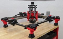
I suggest you to have a look at the MPCNC, it would fit such project nicely. I have built a few myself so I know this machine very well. The MPCNC is cheap to build, it's a motion platform that allows you to put any tool you want and get good results.You can make one of almost any size

Looks like that:
Primo-400x250.jpg

Don't get fooled by the fact that it looks flimsy and all, so far, people have successfully:
-Cut wood, foam and other soft materials (I've done it with this platform)
-Cut aluminum with really decent speeds and great results (been there, done that too)
-Cut Steel, at low speeds but great results too
-Plasma cut steel (I did it, had a hard time fighting EMF but it eventually worked)
-Laser cut, either with laser diodes or CO2 lasers
-Needle cut, for foam and stuff like that
-drag knife cut, for stickers or vinyls
-3D print, (the main application in my case).
-Cut Ice, for some artistic projects

So far, to my knowledge at least, no one has successfully built a real DIY water jet. The guy from applied science did build something approaching, but even though this was really, really impressive, it was still far from a really usable setup. So, who knows, maybe you'll be the first to do it someday ;)

Here is a link to the forum, I post regularly there so if you have any question feel free to ask!
https://forum.v1engineering.com/

And here is a link to the project gallery, to see what has been accomplished with this machine by forum's people:
https://www.v1engineering.com/videos/gallery/

I think that, even if the project of building a DIY waterjet cutter is probably unlikely to be achieved, the MPCNC platform might still be of use to you for cutting aluminum, so you might want to give it a try, especially now that you have a good grasp at the 3D design.
 
Really nice looking machine! :) I'd had to wean myself off following DIY CNC discussions, absolutely fascinating and far too easy to spend every waking hour reading up on countless impressive projects. If it's any use I've got a parametric design for a wire driven table here, same kind of drive used in most scanners. It allows all the motors and fragile bits to be sealed up in one place, I'd done it for a stone polishing machine but it would work for pretty much any dirty jobs or just as an example of the cable operation. I've also got a design for an arm type but it would need a bit of work to finish, basically just a parallelogram linkage to a small and rigid 3 axis machine mounted behind. That was also for stone work, the stone industry is wary of anything too new and fangled so I'd done it to bridge the gap between what's familiar and the benefits of pivots instead of slides when there's evil abrasive grime everywhere. Looks hard to beat that MPCNC machine though, simple and modular plus tried and tested.
 
Thanks guys! Thats just what I need,.. this is what I love about the forum! The MPCNC is just the kind of thing I need, I'll
look into it, thanks for the links. :thumb:

Thanks for your input Stan.distotion, mostly way over my head but informative, sounds like this is all right up youre ally,
and good to know that you can help with all of this when the time comes.

I bought the subject up before, somewhere way back, but I'll post it again since were on the topic. The water jet part isn't
all that hard to do,.. as seen on Youtube, about $300. gets you a quality head unit, and the rest is the pressure washer.

Youtube links; (a bit long in the tooth, just go to the cutting parts)
https://www.youtube.com/watch?v=Lg__B6Ca3jc
https://www.youtube.com/watch?v=qAIDFaKhcZE&t=858s

Not the most powerful thing, but still useful for a DIY project, mostly for cutting thiner parts, and a little slower.
But it doesn't matter what the material is,.. glass, ceramic, Titanium, silicon steel, carbon, or neodymium,.. all get cut.
Mostly I want it for small thin magnets, so I can make precise shaped trapezoids without affecting the flux power.
But it would be great for SMC parts too. I could make delicate small pieces, and it would cut without braking.
 
From what I've heard handling the abrasives is where it gets difficult, reclaiming, screening, feeding, part wear, etc. Like you say though, prices have come well into the diyers range, last time I looked into them was about 6 years ago and a good quality nozzle was about $4k minimum. Pressures are also usually much higher in industrial units, 100k psi+ iirc. Pumps in that pressure range are getting much easier to find but still not cheap, thankfully pressure washers can be picked up for little or nothing so winding a relief valve in to find the breaking point wont hurt the wallet much, safety first ofc but most should hold up at 20k psi or more.

Sorry if I made Gcode sound complicated, it really isn't, it's just instructions, "move at this speed", "move to these coordinates", "turn motor on", "turn coolant on", etc. It can be used like a programming language, logic, routines etc. but very rarely is, even simple stuff like "move in a radius from this point" doesn't get used much because the machine may not understand the instruction so a radius is usually just lots straight lines between points.

You hardly ever need to work with Gcode directly, a lot of CAD programs will do that part and there there are plenty of tools for doing it but there's usually some setup involved, knowing what command turns on the pump and what are the machines travel limits for example. After that you never need to look at it again unless you change something on the machine, just draw it, tell it how you want the job done and send the generated gcode file to the machine.

It's well worth looking into because even really simple stuff like automating a pillar drill and rotating table or just a single linear feed for a plasma cutter or oxy torch can save a mountain of work and it's easy to move from that to powering feeds on a lathe or mill. I wouldn't recommend converting manual machines as a first step though, fitting motors can be a pain in the butt and backlash causes an even bigger pain, the table above is ideal.
 
Tanks Stan.distortion, that's what I need to know. After reading you're previous post's a few times I understand what you
are saying a little more clearer. I'll probably have to get into G code basics a bit at some point, but I'm hoping to find
a board or a program that does it for me from CAD STL or Solid. Once I look into the links it will all become more clear.

Luckily I don't need a high power jet. The stuff I'm cutting in the motors is relatively easy, and softer materials, plus,
I have lots of time to spend on cutting it.

Heres a link to the head unit, although there are offshore versions that are cheaper, they don't have the replacement parts,
or an accessible company with a good history.
https://www.accustream.com/waterjet-parts/accustream/a2/a2-cutting-head.html

If you have a small lathe and mill, a 3D printer, and a simple water jet cutter, then DIY motor building is do-able. So I'm
still missing the one tool.
 
I've been busy sketching Thecoco974's inrunner idea for a version 3 motor, and I'm liking it even more than the outrunner
version. :thumb: This is a mid-drive motor for a mid-drive bike.

Inrunner version V3.png

The two aluminum stator carrier's are solid one piece and easy to turn on a lathe, as well as the axle. The 1/4" thick
rotor is strong and only needs to be sandwiched by the axle by a few centimeters. Very easy to attach magnets, and
they re-enforce each other. It is said that the center rotor axial configuration is the most efficient out of all of them,
maybe this is why.

The only problem I had was figuring out a way to run a drive system off of the axle end, but by using the 40mm ID.
bearing on the drive side, theres plenty of room to make adapters for a six bolt cog, or any other system.

There are many advantages to this design,.. better cooling and phase wire access, mounting options, shorter axle length
and narrower motors, non-rotating body, and switchable wye and delta modes 'on the fly'.

It's also possible to mount it behind the drive cog arrangement, making it easy to remove the chains without the axle
being in the way, which is always nice.

The narrow axle is particularly good for the bikes I'm building, because of heel and toe clearance between the cranks.
The motor is very close to the bottom bracket.

See any problems?
 
Yeah, laminations for example, a deal breaker to most diyers but just sheet steel and time with a CNC cutter. Btw, I'm way out of date with what's happening with CNC machinery these days, it's about 8 years since I was keeping up with it and things where changing very quickly, even 3d printing wasn't a big thing at the time so the best course will be an awful lot different today. Well worth checking some of the info Dui, ni shuo de dui linked but be warned, start looking into it some evening and next thing you know you're wondering why it's getting bright outside ;)

That motor, are the magnets back to back, like poles to the outside? If so that would also work well for a coreless setup if you ever wanted to give one a try, the windings just go up one side and down the other. Stackable too, just keep the windings going on up and down the next rotor and loop them back at the ends. Some half finished plans for a 3d printable one here with a very similar looking rotor, not much more than a cage to support the windings and some back iron.
 
Yea, I have been working on a coreless version in my head, just thoughts at the moment,.. but one of these days.
Definitely multi disc, multi stator, and it would probably a bit wider, but like you say, most of it can be 3D printed,
which is very attractive. I agree, it wouldn't be too much different than the motor above.

So many motors, so little time.... :)
 
Inrunners can be made to mount from anywhere on the case, but I think one good way might be to go directly to the
bearing area, fairly common on many RC motors. This takes all the stress off the rest of the case and connects the
mount to the source

Motor mount..png

This idea uses a steel ring on each side of the motor that can be welded to, but it could also be a plate or something similar.

Not having a thick axle in the middle of the drive system makes it easier to remove chains without braking them, but also
allows the use of a 9-spd freewheel, for more front pedal gears,.. something the previous versions wouldn't allow.

The in runner idea keeps getting better, thanks Thecoco974! :thumb: The only obstacle I can see so far is the ability to
switch back and forth from an outrunner to an inrunner motor type. But by making the frame/motor mounts bolt on,
this wouldn't be a problem by using changeable mounting cages.
 
Well, I like the inrunner a lot, and I think that's the way to go for V3,.. but in the interest of this thread I thought it
would be good to take a peak at what a coreless version might look like, since Stan.distortion just bought it up.

I hadn't given it too much thought, other than I know it needs multi stators, and since Lebowski has built one already,
and he has lot's of real world facts and figures, then that would be a good place to start. (4 rotors, 3 stators.)
https://endless-sphere.com/forums/viewtopic.php?f=30&t=46476&start=25

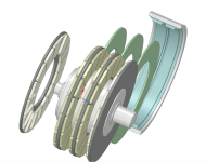
We know that the rotors and magnetics need to be mega-strong, so I made the axle-hub very large and put 'steps' on it
so the rotors can be bolted down solid, and the steps can be turned to the exact air gaps needed. That takes care of all
that.

This sketch has four .250" iron back irons in it, which are super strong, easy to make, and cheap.

Coreless axle-hub..png

Then the coils can be wound in the Marand fashion, and held in place with the plastic spacers so theres no eddy's to the
outer ring spacer of the case, and they get spaced just right too.
Marand website: https://renew.org.au/wp-content/uploads/2018/12/marand_high_efficiency_motor.pdf

Coreless concept..png

Thats about as far as I've gotten,.. if you see anything, or have any ideas, all opinion are welcome. :)
All just speculation,.. so anything goes.
 
Seems like you wouldn't need back iron on the middle rotors if you could figure out a way to hold the magnets. They could even be single layers. But the iron like you show will have some strength, which we now know is very important to prevent deflection.

The age old problem with coreless motors is how to remove the heat from the windings. Granted, if you make less heat in the first place there's less to remove, but this generally becomes the limiting factor. That's a big advantage to the inrunner design where the windings can dissipate directly to the outer case.
 
For the coreless widings, as far as I can tell it can be done much more simply. Screenshots of what I have here, not all that clear but maybe a help:
Cage and rotor:


Windings only, end turns not shown, either carry on up and down for stacked rotors or loop around every 3rd set


Assembly plus a small amount of shielding:


If the magnets are back to back, like poles to the outside, that winding configuration should be correct. An alternative arrangement would be round magnets with steel between, like a doughnut. That would make use of the windings going over the outside as well as the faces but would be a lot harder to machine.

I'd drawn that one up to suit some small rectangular magnets I have here but for a decent controller round magnets would probably be a better option, should give close to a sine wave. Rectangular would probably be the better option with RC ESCs.

I'm not sure how much magnet is ideal, more should give a lower Kv but I've not done much with the calcs, I'd drawn this one up to get a handle on what's happening and see what needs tweaking. Commercially available coreless motors seem to use a hell of a lot of copper in relation to the amount of magnet, that's a really crude way of looking at it and they all tend to be really high rpm but FEMM seems to confirm it, the only way of getting reasonable amounts of torque seems to be masses of windings.

There doesn't seem to me much benefit over using cores, little to no weight saving and craploads more copper. Aluminium windings have been warned against and I'd be wary of them but they seem to be the only option for choosing coreless over cored, there could be a considerable weight saving.
 
Thanks Stan.distotion, for showing that. It reminds me of a fusion reactor somehow,.. very cool! :thumb:
I like the wrap around coils, and back iron.

Yea, trying to get power, or I should say torque, out of these things is the problem, it results in heat, and the heat has
to get taken out somehow. Maybe theres a way to use the internals for that, or the use of small fans.. it is an inrunner.

Lots of steel and lots of copper for sure, I have to wonder if it's worth it just to get away from making cores. But, on
the other hand, it's actually DIY better, as steel rings are cheap and easy. Six of one,.. half dozen of another.

Fechter, It would be nice to be able to go straight through with the magnets, and no back iron, but we know how hard
that would be, and indeed Lebowski had trouble with rotor flex on his build too. It's actually worse, because theres
"magnets attracting magnets"

The winding of the stators isn't easy either, (Marand), in fact it looks like a total pain. Maybe it would be better to use
the traditional bobbin type coils. Makes for a wider motor but maybe not by much. I think the torrid wind has more power
per space though.

Lebowski also said that he thought it is better to wire the stators in series, to compensate for uneven air gaps and
magnetics in a multi stator system. This means higher input voltages, and that means more batteries to get it.
More cost, more space, more weight. Hmmm :(

Well, it's intermission speculation, so one thing at a time. Cooling, and stator types. :?:
 
I didn't notice before, but looking at the Marand rotors, I see that they milled a relief in the centers of the magnets
on the back side,.. something that I suggested a while back. It's good to see that someone else thought it was a viable
idea too.

On a motor with four rotors it might actually save a good bit of weight. And all it takes is a ball-end mill cutter.

Marand back iron relief..jpg
 
One thing to remember though, is that the coreless motor is easier to make into a larger diameter, and in fact should be.
The bike is the limiting factor, but if possible I would go for a 11" or 12" diameter. The larger it it's, the more torque and
less heat to get it. Lebowski's was pretty small, and he was getting 750 watts, this one would be much larger, and have
much more magnet and coil area as well.

As far as coils go, there are several ways to do it. Thinking more about the Marand stator winds, each wire in one magnets
coil span would be separated by two wires of the other phases. So there would only be only 10 or so radial wires per span,
per magnet. :?: Per side though, so maybe that would work out to 20T per magnet pair.

Stan.distortion also has the way he has shown above, which is very nice, but might not be transferable to multi stator
very easy.

I would think that a standard trapezoid coil arrangement might have the most area? Subtracting end turns of course.
Maybe even a flat wire wound coil, for more radial space.

Full coil span wind..jpg
Flat wire trapezoid..jpg

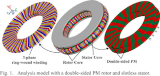
Then the siosudial type that crosses over on top and bottom, and the ring-wound torrid type that wraps around both sides.

Sine-wind coil..jpg
Ring wound stator.png

Another way to do it is to wind all the wires of one coil span together, per magnet. But the logistics of that are not clear to
me, and similar to the rig wound stator.

Single span wind..jpg

I wonder what the best way to do it is?
 
The winding method I'd posted earlier translates very well to multiple rotor, it's pretty much the reasoning behind it. The end turns take up a lot of space no matter which way you run them, the idea with that was to have just 2 runs of end turns, between the rotors they just carry on back up in a U. The wasteful part is where they go over the outer edge of the rotor and that's easy enough to get back by putting the magnets in between steel segments of a rotor, that entire (pizza) slice of the rotor is an N pole, the next an S pole, etc. The next logical step is the same layout as both an inrunner and an outrunner, there's an inrunner rotor between the U in the windings an an outrunner rotor between the n side. Very awkward though and that was aimed at simplicity, the windings all just push on from the outside and a casing/cage holds them in place and has bearing carriers, mounts etc. Screenshot from an earlier sketch including casing:


(EDIT: The bottom side in that pic includes an end turn cover, I haven't drawn the end turns but that's pretty much the area they need for the cross section of windings in the pic. The cover is also intended for cooling, air enters past the end turns or between multiple rotors and exits at the circumfrence of the rotors. Separators for the windings at those points would allow a large surface area of windings for cooling but air flow over the rotor surface probably wouldn't be great.)

Winding surface area is only part of the issue with coreless, cross sectional area needs to be seriously big, craploads of windings and the end turns become a major pain as they get bigger. Winding bobbins is the simplest approach, probably the best for a prototype and maybe fairly simple to try out with your current build but it needs a crapload of copper, the entire stator area wouldn't be unrealistic.

Another edit: Have you played around with FEMM since getting a handle on CAD? The drawings are the hardest part and you can just import 2d dxf files for that, the rest is just getting familiar with it and imo it's pretty simple. I'm no expert with it, only a very basic understanding of both the app and the science behind it tbh but it's plenty to work on and to see how powerful those kind of tools can be in motor design.
 
I see what your doing now, sort of winding across the motor, and crossing to the next coil on the ends,.. or the sides
of the motor. Then you can slide them on and off radially.

Is the iron in between them necessary? I can see why you would want an outrunner rotor there. That would make
the design complicated though. The back iron (or rotor) would have to be two piece in order to get the coils out.

Yea, the crossover on the top, or diameter,.. but like you say, could put it to good use with magnetics. If you could
make the rotors thin enough though, there might not be that much of a span maybe.

I'm trying to visualize it on my sketch, but haven't made it work yet. I think it's probably bobbins that will be the best.
They can be 3D printed, and are easy to understand and change out,.. things that are desirable with DIY.

Marand style is nice, but difficult to do. All the turns have to fit exactly right in the 360 degree span. Can't have a few
more or a few less. You might get close to the end and have to redo the whole thing. I don't like it.
All of the other winds are somewhat like that as well, theres no fudge factor. With bobbins, you can get everything to
fit exactly right, from the start

I guess my question was, would one of the wind styles above pack more Lorentz force potintial than another? Otherwise
standard trapezoid coils are probably the easiest, and most often used. They also allow you to wire the motor up
the way the motor winding calculator suggests, with some windings reversed.
 
In FEMM that little bit of back iron adds considerably to the torque output, iirc I tried the windings in a multiple rotor in FEMM and the opposing windings cancelled each other out but I'd have to double check that. That's the most obvious weak point in the layout so any advice appreciated! The back iron would need to be laminated and probably need a deep dish to cover the end (rotor circumference) turns.

If it could be just slightly dished to cover the flat part of the windings (as drawn) then it would be very simple to make, just thin disks and as far as I know that would be ok for magnets on either side of the rotor but a full enclosure would be needed for a fully magnetised rotor, (ie. magnets at 90 deg between segments of a sliced doughnut rotor).

As far as I know the end turns do absolutely nothing with coreless (again, any advice appreciated, total noob with this stuff and very little of it seems intuitive). It works by the magnetic field rotating around the conductor, a magnet in that field will be pushed in the direction of rotation (90 deg to the conductor) so a conductor in line with the rotation of the rotor will just try to push the rotor off centre, not around and radial windings will do the opposite, all the push will go into rotation.

EDIT: Sorry, forgot to mention, yeah, the windings are just pushed on from the outside in that layout. I think it would be possible to use one piece backiron (and whatever retainers etc.) with the windings just wound to the correct length and formed in the slots (threaded through the backirons and pushed into the slots) but I'm not sure. They'd certainly be better quality with formers made so everything's wound to the correct shape to just slot in but like you say, that would need split backirons and whatever other complications.
 
As they say, all motors are a compromise. No matter which way you move, it adds complications elsewhere. They are
always just the best middle ground balance. It's good to see your thinking outside the box a bit, I think thats what it
takes, and we learn so much by doing it. Curiosity keeps us going, and leads to more knowledge.

Theres nothing simple about motors, except that theres only two parts. The one that stays still,.. and the one that turns.
After that, it's all complicated.

I haven't ventured into FEMM yet, I guess I have enough headaches just trying to get a good grip on the basics at the
moment. I'll get into FEMM a little later for sure,.. but I have plenty of simpler things to think about for the moment. :)
 
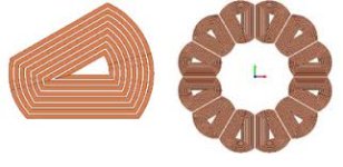
Keeping with the 3D printed stators idea, I started drawing one up, and realized that the spacers could be built in.
Then I thought maybe they could fit into each other and stack. Each half has 9 coil sockets and they mesh together.
I still needs some room for the wiring yet, but after that the two sides can be glued together, and slid into place.

The steps on the axle won't allow the rotors to slam together, so assembly is safer, and the stators get placed in between
them. Once that's done, the unit is slid into the outer case ring, and everything is self aligned when the covers are on.

3D printed stacked stators.png

Coils get pushed into the sockets, and might even be able to get some cooling through them too, with electric fans.
Gee, this might actually be an easy motor to make,.. the cost is in the 96+ magnets though.
 
In this sketch I've added some axial cooling fans to the side covers, for a push-pull radiator style air flow from one side
to the other. I'm not sure if they have the power to do it, but it's all I can think of for now. There needs to be a little
longer axle on the drive side for clearance though.

Coreless cooling fans..png

All in all, there doesn't seem to be an advantage to this coreless design other than 'not' making cores and dealing with
the strong magnetics that comes with them. The motor is is longer, with about a 100mm case, and heavier with 4 rotors
and lots of copper, and the 90+ magnets are going to cost $450. at least, and weigh quite a bit as well.

The two end rotors are 10mm thick, with magnets, and the two inner rotors are 15mm thick. The 3 air gaps are 11mm
each, and there needs to be room between the side covers and outer rotors for air movement.

To be fair though, it is an easier motor to make, needing only a lathe and a printer, easier to assemble, and the power
output may be quite good, but is unknown. It could be estimated in FEMM though. It doesn't necessarily need to have four
rotors either.

An interesting motor, and fun to explore, but I'm still partial to the cored in runner that Thecoco974 suggested, at the
top of this page.
 
I'm not sure, are those green parts that hold the coils supposed to be 3D printed?
If yes, I wonder what material you plan to use, since plastic would melt quickly and wouldnt be even close to the kind of strenght you'd need to keep those coils from moving.
There's probably something I didn't understand in your drawings.
 
Yea, that was the plan,. 3D print the coil holders. I guess I'm not sure what kind of force the air coils produce. Much less
than cored for sure, but how much less? (1/3rd?)
I know that Lebowski used .250" plexiglass for his stator plates, and mostly drilled with holes, but this is a larger motor.

I would think that a 'boxed in' and bonded set of cage halves like this would come close to that strength? It depends on
how thick the side walls can be made I suppose. Theres an 11mm gap between the magnets, so the walls would depend
on the coil size needed.

An 11mm gap would need 8mm thick coils for 1mm walls. I think thats about 4 turns deep of 14Awg wire. As far as coil
turns and size wire goes for this kind of motor, I don't have a very good idea, and it depends on the volts and RPM.
I'm mostly trying to show a physical way to make it.

As far as temperature goes,.. I'm not sure about that either. ABS is the strongest print material, I think, and I don't know
what kind of heat it can take. So you may be right.

What kind of heat can we expect to see from a motor such as this, is the question. I would think that a 1 to 2Kw input
would be reasonable, spread out over three stators with 18 coils each.

The two sides get glued together, so that makes it stronger, but would it be enough? Once again were stuck with too many
unknowns. But it would be easy to print one up and find out. The stators are the easiest part of this motor if they can be
printed.

Theres always the solid fiberglass plate stator idea, if printing wouldn't work, but I think that needs to be drilled out for
the coils too.

3D printed coreless carrier..png
 
Back
Top