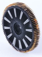
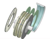
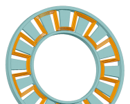
APL's DIY axial-flux motor

I just saw this Youtube vid on making a fiberglass stator, using the Marand style winding, and realized that if it's all pre
set up with pins, then you can't get the windings very far off skew. He has a lot smaller rotor, and it's a generator, but
the magnetic forces on the windings should be the same. Still don't know how much that is though, so once again,
a bit of experimenting would be in order to see if 3D printing stator carriers would work for air core motors. Especially
larger ones like this, with more power demands, and heat.

https://youtu.be/RiiP5mDVqLo
 
I don't see how it wouldn't, but it depends on distance as to how much. If it's a few cm away it might be minimal. In the
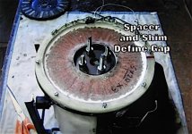
next video he shows the axle, and it's mostly spacers.

Stator clearance..jpg

https://www.youtube.com/watch?v=GN1y5jDbx2s&t=98s
 
Lebowski said:
If you make the winding basically a big circle around the axle, wont you induce eddy currents and losses in the axle iron ?

Maybe.

APL said:
I don't see how it wouldn't, but it depends on distance as to how much.

I don't think distance matters.

However, if that "circle" around the steel carries a balanced 3-phase current, would any eddy currents be induced in the shaft steel?

major
 
Shouldn't be much different from any other axial coil arrangement, still a circle of 3 phase coils around some steel or
aluminum parts, right? Maybe I'm missing the point.

I looked at the Marand again, to see what they had going on, and it looks to be a steel hub but farther away than the
video build. They keep their back iron to a minimum too.

I wonder if the back iron has a smaller ID than the windings, as in the video above, then would it create problems as well?

Marand; https://renew.org.au/wp-content/uploads/2018/12/marand_high_efficiency_motor.pdf
 
APL said:
Shouldn't be much different from any other axial coil arrangement, still a circle of 3 phase coils around some steel or
aluminum parts, right? Maybe I'm missing the point.

The difference from most other axial coil arrangements is they use closed loop coils whereas this guy has essentially "open loop coils". In other words, the 40 armature coils are not each closed loops on themselves. All 40 coils close just once.

The big circle, as Lebowski puts it, is like a 3-phase transmission line. In such, the current vectors cancel and result in little to zero magnetic field outside of the 3 line bundle. The distribution of the phases in the winding produces a rotating axial magnetic field where the flux cuts through the phase groups.

If there is no magnetic field inside Lebowski's big circle, then distance to steel is academic. But if there was a changing magnetic field from the big circle, it's strength would be constant over the enclosed area, ampere-turns, right?

major
 
OK I can see the open and closed loops. So are we talking 3 phase induction coil, and any ferrous material at it's center is
affected? I can't quite envision your field yet, but I still think that the affect would diminish with distance.

Maybe I 'm not understanding something, that's usually the case, I'm pretty sure that I've seen a few motors with this
kind of winding, with metal axle parts though. Or maybe I just never noticed, so I'll have to go back and take a look.

The only thing I'm sure of, is that I'm not sure of anything. :)
 
APL said:
Yea, that was the plan,. 3D print the coil holders. I guess I'm not sure what kind of force the air coils produce. Much less
than cored for sure, but how much less? (1/3rd?)

The two sides get glued together, so that makes it stronger, but would it be enough? Once again were stuck with too many
unknowns. But it would be easy to print one up and find out. The stators are the easiest part of this motor if they can be
printed.

I'm 99.99% sure this cannot work. :(
But what could be done however is to 3D print a mold and then use this mold to cast epoxy withglassfiber.
 
Well, you know more about printing than I do, and a feel for it's strengths and weaknesses, so I'll assume you're right.
Making a mold out of it is one way for sure. I was thinking that you could maybe just fill the print and coils with glass and
resin? Not completely per say, but enough to get the strength needed, and allow for some heat/air transfer through the
coils & holes. I don't know if print material bonds well with glass resin though.. might have to be a mold..

The two issues here are strength and heat. Heat wise, maybe any print material in the structure is a no-go? There would
still be a lot of it. Strength wise though, I think the two together would be strong enough if possible to do.

3D printed coreless carrier. copy.png
 
APL said:
OK I can see the open and closed loops. So are we talking 3 phase induction coil, and any ferrous material at it's center is
affected? I can't quite envision your field yet, but I still think that the affect would diminish with distance.
...

Hi APL,
Without straying too far off-topic, envision a clamp style ammeter. Like this:
how-to-measure-current.jpg
Image from: https://www.fluke.com/en-us/learn/blog/clamps

When both leads pass thru, it reads zero. Because the current vectors cancel. Same with 3-phase. You need to clamp around one leg only to get flux in the iron ring to activate the Hall device. Also, there is no significant difference due to the position of the conductor inside the iron ring.

Apply that analogy to Lebowski's big circle in the motor.

major
 
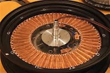
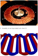
After looking at many motors with sinusoidal windings in a 360 deg. circle, they all have steel and aluminum centers.
Usually spaced at least 3-4 cm from the coils. So, I would think that either they all have axle/eddy current issues, or
that the effect is minimal, and not a problem. :?:

Coreless stator.jpg

Coreless stator 2.jpg

Theres a lot I don't understand about this style winding, and would really have to do a lot of research before I ever
considered making one, which is why I prefer the idea of using standard trapezoid coils, but I can see where using
a sinusoidal winding might have the advantage in power density, and maybe the controller type.
 
The key is where the flux is going. In the motors, pretty much all the flux is staying between the windings and the rotor. Not much is going to be going around the shaft. If you had a ring winding that was just round, then you could get some flux around the shaft depending on the magnetic structure.

I've seen some transverse flux motors where the winding just looks like a big round coil, but the flux is carried by the stator iron such that none of it is going to be around the shaft. If you had a round coil and NO stator iron, then you would have significant flux and eddy losses around the shaft.
 
Thanks for shedding light on that fechter. I was thinking that there must not be much flux making it to the axle.

Looking at the photo above, I have to wonder why he's using two separate stators in that fashion though. Is he
trying to get double the torque from two stators in the gap? I have to wonder if the inner windings might cancel
each other out. If not, then I find it an interesting idea, although I have to wonder how much the inner windings
would contribute to the force.

Double distributed winding stator..jpg

Taken from; http://build-its-inprogress.blogspot.com/2015/02/coreless-axial-flux-motors.html
 
With a single layer, the inductance of the coils will be so low that it will cause problems with many controllers. I'd guess it's just a way to get more turns. I've seen some designs where they just use a water jet on a thick plate of copper to make coils. It takes several layers that need to be welded or otherwise attached by very low resistance connections. Similar approach to using printed circuit board coils.
 
I see, that makes sense, I think he wound up running them in series, which made the motor run slower. I've seen the
printed circuit style windings a few times, and I think they have some issues with crossover windings on a 3 phase
arrangement, but it's an intriguing idea non the less. To bad we can't 3D print copper yet.

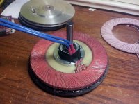
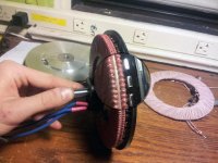
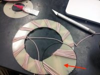
One thing that I kept thinking about was how he was dealing with the crossover issue between each of the coils in a
phase, since the winding was being wrapped around a disc. Then I noticed one of the photos, that shows the other side
through the fiberglass. It goes at an opposite angle. (I thought he would just run one wire over to the next coil.)
I have to wonder if this is also a reason for the dual stators,.. to get the outer windings in the correct direction. :?:

Stator winding pattern..jpg

One thought I had with the water jet cut copper coil, was to bond each phase layer to a separate sheet of .020" glass-
board, and layer them on top of each other. You could keep going with the concept setting each new 'set of three' 15
degrees apart from each other, until the 11mm gap between the magnets was full. Bond all the layers together, and run
them in series.

Heres the final blog for the motor, in case anyones interested; http://build-its-inprogress.blogspot.com/2015/02/finishing-up-coreless-motor.html
 
Taking a look around, I find quite a bit of info on printed coils, mostly for small motors, but I think that the process
is 'etching' for removing copper from the board. I think that it can be used for thicker copper too, and may be an
alternative to water jetting, but I'm sure it has limits.

etched stator coil.png

Something that looks right about it. Interesting, as it lets you design optimal geometric coil patterns that you can't do
with wire.

I thought that maybe a 3D router table might be the perfect tool for the job too, and wouldn't require any chemicals
or mask's. Especially for thicker copper.

I found an article about printed coils for the archives, it gets long and technical as usual,.. but the first few paragraphs
are a good intro.

https://www.pcbway.com/blog/Engineering_Technical/Designing_Printed_Circuit_Stators_for_Brushless_Permanent.html
 
I guess the correct term would be, PCB axial motor, and the Image search has a lot of links to this type of technology.
https://www.google.com/search?hl=en&tbm=isch&sxsrf=ALeKk02TL-jKuNpglQYWPGbIiizr2Sx0aA%3A1606681589441&source=hp&biw=1680&bih=1012&ei=9QPEX5O8GJi6tAaFkbGABQ&q=pcb+axial+motors&oq=pcb+axial+motors&gs_lcp=CgNpbWcQDDoECCMQJzoFCAAQsQM6AggAOggIABCxAxCDAToGCAAQCBAeOgQIABAeOgQIABAYULsZWOOSAWDKswFoAHAAeACAAYsCiAH1D5IBBjEuMTMuMpgBAKABAaoBC2d3cy13aXotaW1n&sclient=img&ved=0ahUKEwjTip2ry6jtAhUYHc0KHYVIDFAQ4dUDCAY

Another approach is this "machined" coil prototype, where the coils fit into each other to form a flat stator. A very
interesting article, and hard to believe that they did it, although ultimately it suffered from high copper losses and
would require a bit more development.

Most of the coreless motor builds that I've seen suffered from copper losses, or heat issues in one way or another. I'm still
not sure if they have any advantage over a cored motor yet. I suppose it depends on the application, production, rpm's,
etc.

Machined copper coils..jpg

Taken from this link, shown here before,.. and a little hard to find. Might load up a little slow at first too.
https://ntnuopen.ntnu.no/ntnu-xmlui/bitstream/handle/11250/258043/759964_FULLTEXT01.pdf?sequence=2&isAllowed=y
 
Solid copper coreless motor are interesting for HIGH copper density but are not usable for high RPM, because of Eddy currents losses, they are only aimed at hydraulique motor remplacement.
Eddy currents are rotating currents created by moving magnetic field over a conductive material and are proportional to the width in the direction of movement.
To make a usable coreless design, thin wire must be used (in form of litz wire usually). Doing just that lead to pretty efficient design as shown in the blog you linked above, he ended up with a figure of merit slightly ahead of the well known melon outrunner.
But as you said the cooling need to be adressed for continuous power mailing.
For that issue launchpoint design is pretty cool since it uses the motor itself as a centrifugal fan to cool itself (i'll do something like that with mine) but start to be effectiv at some speed.

Envoyé de mon Redmi Note 9S en utilisant Tapatalk

 
I can see that if the copper has a large surface area facing the magnets, there will be a lot of eddy currents in the copper (bad). Well, skip the copper plate idea. Litz wire, which is a bunch of really skinny strands in parallel, will minimize this. If the copper was a flat strip and placed on end so the skinny dimension was facing the magnets, it would be much better than having the wide side facing the magnets.
 
Could maybe use some 1/4" copper square/flat wire, sideways, (skinny), and machine the phases to fit together. :?:
Theres 11mm in the gap. It would need to be cast in resin to have any strength, and it might be a little hard to figure
out the gauge of copper, for three stators. Then theres the cooling issue, of course. Just a thought.

I have to wonder what size and length of Litz wire would be needed too, for a multi stator motor such as this.

I looked at some Litz wire prices, and it might add a lot of cost to the motor depending on the size and length used.
That stuff isn't cheap. I don't know what size would be used, but 14 awg Litz is $570. for 5 lbs. / 80ft.
The Litz is also thicker than solid wire at .090."

The cost of magnets is also high, with a four rotor motor, and 20P = 100 magnets. So even though the motor might be
easier to make, it could get a little pricy, unless those prices can come down. An expensive experiment,.. so the power
output would need to be better known beforehand.
 
In a multistator design the intermediate rotor only need magnets on one side, but it's more chalenging to mount them and make it strong.

Envoyé de mon Redmi Note 9S en utilisant Tapatalk

 
http://educypedia.karadimov.info/electronics/javamotordc.htm

Have a dig about on there for visualization reference.

For the shaft to become hot it has to be inside an inductive loop when its one single coil surrounding the entire shaft like an inductive loop for a mechanic etc but when the shaft has multiple coils around it they cancel out each other the shaft only stores the eddys from the first phase fire and gets cancelled on the opposing phase fire so its equilibrium I'd of thought.
 
Thecoco974, yes, I was thinking about that, the center rotors could be nonferrous and save a some of the magnet cost,
if it could be made strong enough. Since the gap is usually around 11mm, it may be possible to do, but would need
some experimenting, it would sure be nice to loose the back iron weight too.

Theres virtually no room between the magnets though, so I'm not seeing how to do it yet.

I think that the sideways copper stator coil idea is basically what the Lynch motor is all about, although I'm not sure.
I think that instead of having a continuous phase wire, they use brushes on the inside diameter, that rewires the coils
as it spins. :?:

Lynch motor..jpg

It's probably not possible to have three flat wire phases like that in one gap, because the machining to fit them together
would reduce the strip width. But I was thinking that since theres three stators, you could put 'one' heavy duty flat wound
phase coil in each magnet set, or stator plate. :?: (index the phases)

Coreless concept..png

Might even be able to double or triple each winding as well, since there would be room as a single phase,.. to get more
wire length, and Lorentz. The controller would need to see a higher phase resistance than a single flat wire winding
would provide.

If the center part of the wire could be exposed enough, like the Lynch motors, then better cooling might be possible too.
 
Thanks for the link Ianhill, it looks like a good source to dig around in! Going to take a while though... :)
 
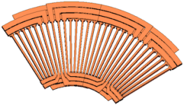
I drew up a visualization of what I was talking about. Looks like an ancient Sun symbol. :)

I'm not sure about wiring each of the consecutive radial wires in series yet, haven't quite figured that out, but this shows
the cooling windows anyway, and the general idea of the thing. Three of these,.. one for each phase. One for each pair
of rotors. :idea: :?:

One phase stator, 6 -8mm wide copper flatwire strip. 11mm gaps.
Flat wire stator..png

I drew three radial wires, but it could be many more, depending on how thick the copper was,.. could use thin sheet too.
Plausible?
 
Back
Top