
You are using an out of date browser. It may not display this or other websites correctly.
You should upgrade or use an alternative browser.
You should upgrade or use an alternative browser.
Bafang M500/M600 thread
- Thread starter El_Topo
- Start date

casainho
10 GW
- Joined
- Feb 14, 2011
- Messages
- 6,058
So, as ESP32-S3 has a CAN controller, the external board to have CAN and connect to the torque sensor, is much smaller and needs less 2 wires, so simplifies the EBike DIY board - here is the updated schematic:

Here is the torque sensor testing firmware on the repository: https://github.com/OpenSourceEBike/EBike_EScooter_app_pyhton/tree/main/firmware/testing_firmwares
The torque sensor testing firmware running and printing the torque sensor values:

And here is the EBike board, with only the circuit to read the torque sensor and connected to it:

More details of the board:


And the torque sensor connector pins:

Here is the torque sensor testing firmware on the repository: https://github.com/OpenSourceEBike/EBike_EScooter_app_pyhton/tree/main/firmware/testing_firmwares
The torque sensor testing firmware running and printing the torque sensor values:
And here is the EBike board, with only the circuit to read the torque sensor and connected to it:
More details of the board:
And the torque sensor connector pins:
Beggel1969
1 µW
- Joined
- Jan 5, 2023
- Messages
- 2
Hello everyone.
So I managed to get online access to the BesstPro software via the bypass. Now I want to reduce the max tempo in my M510. Since the program is still fairly new and has since been removed online, I can't find any instructions on how to do it. The display and controller are also recognized when reading, but if I want to change the parameters in the settings, the numbers entered are reset and a reading error occurs.
Best Regards
Ulrich
Waynemarlow
10 kW
Pro only works with the last version of the firmware, I'm not sure the M500 didn't have the earlier version that is not changeable from the BeestPro. Both the earlier version of the M500 and the M600 motors seem to have been cast off into the no longer updateable motor section by Bafang which is not good for PR by Bafang.
The most info on this seems to be here, you may need to follow it back through for a few pages but the info was there of which versions the Pro worked with.
https://www.emtbforums.com/threads/bafang-m500-and-m600-motors.18717/page-21
The most info on this seems to be here, you may need to follow it back through for a few pages but the info was there of which versions the Pro worked with.
https://www.emtbforums.com/threads/bafang-m500-and-m600-motors.18717/page-21
casainho
10 GW
- Joined
- Feb 14, 2011
- Messages
- 6,058
I can not read the wheel speed sensor and the throttle. Can anyone help here?? I am using this pins but I should be doing something wrong to power up and read the wheel speed sensor, as also the throttle:

Meanwhile I quickly built a display with ESP32-S2 + the OLED 1.3 inches screen, so I can have a display that I can quickly program wirelessly -- here the initial test for menus, in the hope to be used for the configurations:
https://www.youtube.com/shorts/dRrJlFh_L80
[youtube]dRrJlFh_L80[/youtube]


Meanwhile I quickly built a display with ESP32-S2 + the OLED 1.3 inches screen, so I can have a display that I can quickly program wirelessly -- here the initial test for menus, in the hope to be used for the configurations:
https://www.youtube.com/shorts/dRrJlFh_L80
[youtube]dRrJlFh_L80[/youtube]
casainho
10 GW
- Joined
- Feb 14, 2011
- Messages
- 6,058
Finally I were able to figure out the issue I was having to read the wheel speed sensor and the throttle - here is the final pinout of the Bafang M500/M600 big white connector:

And the final schematic:

And the testing sensors firmware:

Now I will make the final wirings and finally put the board inside the motorm including sealing everything with silicone as I will riding on Sunday with mud and probably rain.
And the final schematic:
And the testing sensors firmware:
Now I will make the final wirings and finally put the board inside the motorm including sealing everything with silicone as I will riding on Sunday with mud and probably rain.
casainho
10 GW
- Joined
- Feb 14, 2011
- Messages
- 6,058
The EBike board is ready and attached on the 3D printed motor cover.


And here is the EBike board alone (including the magnetic encoder sensor green board):


I wish to make the board robust to vibrations and water. Since I can program the board by wireless, maybe I will cover the board and wires with silicone, like potting the electronics, here an example:

And here is the EBike board alone (including the magnetic encoder sensor green board):
I wish to make the board robust to vibrations and water. Since I can program the board by wireless, maybe I will cover the board and wires with silicone, like potting the electronics, here an example:
NoFanBoiz said:No Beest tool required.
E-bike setting wheel diameter and releasing speed limit programming line specially BAFANG M600 M500 M510 etc. CAN protocol motor
https://www.aliexpress.com/item/1005004391889323.html?gatewayAdapt=Pc2Msite
but you still can't program motor to your liking ...
casainho
10 GW
- Joined
- Feb 14, 2011
- Messages
- 6,058
So, after the night, the silicone got hard as expected. Note that I also protected the connectors with silicone:

And here is the very first test. I had to increase the length of the battery and motor phase wires, doing extensions. With that, all seems good:

And now testing if everything works well - I have the display connected where I can see for instance that brakes are working:
https://www.youtube.com/shorts/Lfc3q5_oToY
[youtube]Lfc3q5_oToY[/youtube]
And the throttle code, I added it for the first time. There is not specific throttle curve yet:

Next step is to put the final black silicon to make sure everything is water prof. Soon I will be riding :thumb:
And now the best news!!
I received the VESC Flipsky Mini FSESC6.7. It is small enough to be placed inside the motor case, as seen here:

With the experience I now have, I am pretty sure I can build a smaller EBike board to put on top on that VESC, and put everything inside the motor case!!
But my current battery is a 14S / 52V, so I would need to build another battery as 13S / 48V, to work with this VESC as max battery for it is 13S.
So for now I will keep my current build, with VESC Flipsky 75100 placed outside of the motor case. I will also ride and have fun, and if everything goes well, then I can do this improvement. Meanwhile, I will also be building the display, mainly developing the firmware for it -- previous version, the firmware was developed in C and on this new version, will be in Python.
And here is the very first test. I had to increase the length of the battery and motor phase wires, doing extensions. With that, all seems good:
And now testing if everything works well - I have the display connected where I can see for instance that brakes are working:
https://www.youtube.com/shorts/Lfc3q5_oToY
[youtube]Lfc3q5_oToY[/youtube]
And the throttle code, I added it for the first time. There is not specific throttle curve yet:
Next step is to put the final black silicon to make sure everything is water prof. Soon I will be riding
And now the best news!!
I received the VESC Flipsky Mini FSESC6.7. It is small enough to be placed inside the motor case, as seen here:
With the experience I now have, I am pretty sure I can build a smaller EBike board to put on top on that VESC, and put everything inside the motor case!!
But my current battery is a 14S / 52V, so I would need to build another battery as 13S / 48V, to work with this VESC as max battery for it is 13S.
So for now I will keep my current build, with VESC Flipsky 75100 placed outside of the motor case. I will also ride and have fun, and if everything goes well, then I can do this improvement. Meanwhile, I will also be building the display, mainly developing the firmware for it -- previous version, the firmware was developed in C and on this new version, will be in Python.
beemac
10 kW
casainho said:So, after the night, the silicone got hard as expected. Note that I also protected the connectors with silicone:
I just know if I did that - I'd definitely have forgotten to solder something important!
Looks good, it is annoying that the minis are so picky about voltage. I'm going to see if there's a way of me fitting a larger VESC (that supports >60v) if I cut the controller housing down and attach the vesc to the shell of the motor. Would get slightly better cooling for the controller too. Would be a shame to go from 14s to 12s...would much rather go higher than 14s. I know you can potentially use 13s but the docs and other things I've read say that's risky and 12s is safest.. you comfortable with 13s?
For testing - I'll use one of the 1200W DC-DC converters I have to keep the voltage within limits, pretty sure they aren't just boost despite the name.
casainho
10 GW
- Joined
- Feb 14, 2011
- Messages
- 6,058
I think that once we configure VESC to have regen / brake current to 0 amps, as also max cut off voltage less than the max 60V of this VESC, maybe it will work.beemac said:Would be a shame to go from 14s to 12s...would much rather go higher than 14s. I know you can potentially use 13s but the docs and other things I've read say that's risky and 12s is safest.. you comfortable with 13s?
I have chargers for 5A to both 13S and 14S, so I would like to keep on this battery values. I carry with me this chargers on long rides, as they charge fast the battery, 30 minutes will charge 25% of my battery. And 25% of my battery will be good for me to ride for 2 hours.
casainho
10 GW
- Joined
- Feb 14, 2011
- Messages
- 6,058
Well, I tested before. And the code for testing the sensors is really helpful. Maybe the firmware should do this kind of tests at boot and report to users if some sensor has unexpected values.beemac said:I just know if I did that - I'd definitely have forgotten to solder something important!
Detail of the squished silicone, after tightening the engine cover:

I went for a test ride - it works very well: pedal very sensitive, fast response and high torque:

I am not very happy the way that cables come to outside - I can improve that a lot. But, why bother if soon I may jump to have the new version with both VESC + EBike board inside the motor case?? For now I will just put there silicone on hole and wires, to make sure it gets water prof and then I will be riding 8)
@casainho
I've updated the 'overall' image of the OEM board with some of the additional info you had for the pin connectors. You did decode the mysterious SL (Brake Switch) and ZB (Throttle) pins. Several others (grounds) are in line with what the board markings show.
Though curious on a few pins: Though possibly you have just rerouted/changed these for your use?
Pin 1 - You show "Display 5V", the board is labeled B+ (I thought at one time, I measured bat voltage here)
Pin 11 - You show "Speed Sensor 3.3V", the board is labeled 5V
Pin 12 - You show "Throttle 3.3V", the board is labeled 5V
Also curious that there are SPD and SPD2 pins. You've identified SPD as a wheel speed sensor. Does it seem SPD2 is giving a duplicate signal? Or possibly some other speed? Motor speed?
Anyway, here is the updated image.
Attachments

casainho
10 GW
- Joined
- Feb 14, 2011
- Messages
- 6,058
Pin 1 is one pin that goes to display, I decided to use it for the 5V.4πr^2 said:Though curious on a few pins: Though possibly you have just rerouted/changed these for your use?
Pin 1 - You show "Display 5V", the board is labeled B+ (I thought at one time, I measured bat voltage here)
Pin 11 - You show "Speed Sensor 3.3V", the board is labeled 5V
Pin 12 - You show "Throttle 3.3V", the board is labeled 5V
Also curious that there are SPD and SPD2 pins. You've identified SPD as a wheel speed sensor. Does it seem SPD2 is giving a duplicate signal? Or possibly some other speed? Motor speed?
Anyway, here is the updated image.
Pin 11 goes specifically to the speed sensor power pin. I tested and the speed sensor both works with 5V and 3.3V. So I decided to go with 3.3V.
Pin 12 same as Pin 11, but this goes specifically to throttle.
I do not know what is SPD2 pin for. No, motor speed is calculated from the magnetic encoder sensor!!
Great that you updated that image. I used it to check my findings and it was very important - now, can you please submit it to github?
And I did finish the display. The schematic is so simple!! Only 11 wires to solder:
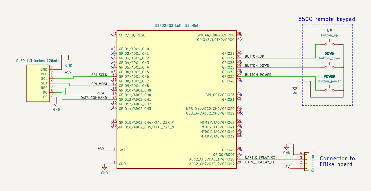
I already tested and it works. Early tests showing the state of POWER, UP and DOWN buttons:

It is not yet fully assembled because currently is waiting for the silicone to harden:

When installed on my handle bard, will be like this, and fully water prof:


Details of the build.
One connector is the display connector to the original Bafang M500 harness cable. The other round connector is to connect to the 860C display remote keypad I bought on Aliexpress:


Very clean and simple:

And now there are two wireless devices connected to my home wifi router, one device is the ESP32-S3 from the EBike board and other device is the ESP32-S2 from this display. I can select which one I want to edit the Pyhton firmware or simple open a second window to select the other board and so have access to both Python firmwares at the same time -- that screenshot is from my phone! I am really amazed to have such advanced technology!!

casainho
10 GW
- Joined
- Feb 14, 2011
- Messages
- 6,058
I did a mistake, I 3D printed the motor cover with PLA plastic, that is a bio plastic but gets soft at low temperatures like 55ºC - but the motor metallic enclosure should get near 90ºC, I think. I will need to print again but this time with ABS that can withstand 100ºC.
But because I did put the silicone on the boards and wires, it will be hard and take more time.... so, why not instead doing the new version were VESC and EBike board will be inside the Bafang??
Luckily, the ESP32-S3 board I use, can be placed on top of this VESC and the VESC connectors will still be accessible:

And also, all this are ok to go inside - I just hope wifi will still working with board on that place:

So in next days, I will start building this new version. I also have in stock a 13S / 48V battery, so for a start, I have everything in place.
And I got the display installed on the handlebar. For now, basic firmware to show assist level, battery voltage e motor power. That is really great the wifi programming, I have the EBike near my desk and I program the display without touching it, wireless:

But because I did put the silicone on the boards and wires, it will be hard and take more time.... so, why not instead doing the new version were VESC and EBike board will be inside the Bafang??
Luckily, the ESP32-S3 board I use, can be placed on top of this VESC and the VESC connectors will still be accessible:
And also, all this are ok to go inside - I just hope wifi will still working with board on that place:
So in next days, I will start building this new version. I also have in stock a 13S / 48V battery, so for a start, I have everything in place.
And I got the display installed on the handlebar. For now, basic firmware to show assist level, battery voltage e motor power. That is really great the wifi programming, I have the EBike near my desk and I program the display without touching it, wireless:
casainho
10 GW
- Joined
- Feb 14, 2011
- Messages
- 6,058
Good news to get AS5047 working with the FLIPSKY Mini FSESC6.7
With the FLIPSKY Mini FSESC6.7, I got no issues at all to get the AS5047 working. I just wired it and it works!! This makes way easier to this project. I wired like this and tested a few times with a magnet near the AS5047:

casainho said:To get the AS5047 magnetic encoder working with Flipsky 75100, I had 2 issues:
1. The SPI wires to read the AS5047 are the same for the hall sensors and so the low pass filters (capacitors and resistors) on the hall sensors circuit (inside the Flipsky 75100), had to be removed. After this, the hall sensor / SPI wires can only read 3.3V signals, so I had to configure the AS5047 board to work with 3.3V (I took the 3.3V to power the AS5047 board, from the EBike board).
2. Two hall sensor wires are incorrect labeled on Flipsky 75100 documentation - HALL 3 should be swapped with HALL 1 (what would be SPI SCK and SPI CS wires, need to be swapped).
With the FLIPSKY Mini FSESC6.7, I got no issues at all to get the AS5047 working. I just wired it and it works!! This makes way easier to this project. I wired like this and tested a few times with a magnet near the AS5047:
casainho
10 GW
- Joined
- Feb 14, 2011
- Messages
- 6,058
So I removed the previous version where VESC Flipsky 75100 was placed outside:


Everything seems good. This 3 D printed cover + silicone seem good to the task.
I finalized the build using the very small VESC FLIPSKY Mini FSESC6.7 -- the way I took the pictures, it is hard to see the VESC under the EBike board. The final result is very small!!


But even so small, it is hard to put everything inside:

Ok, here seems almost good here. I just need to put the 3D printed cover.
But is missing the magnetic encoder sensor board... So, in the limit, it will work as it is but in sensorless mode. But my next step is to add the magnetic encoder board and let's see if it will work. I will also add silicone to the connectors, to make them solid and isolate the electric contacts.

Everything seems good. This 3 D printed cover + silicone seem good to the task.
I finalized the build using the very small VESC FLIPSKY Mini FSESC6.7 -- the way I took the pictures, it is hard to see the VESC under the EBike board. The final result is very small!!
But even so small, it is hard to put everything inside:
Ok, here seems almost good here. I just need to put the 3D printed cover.
But is missing the magnetic encoder sensor board... So, in the limit, it will work as it is but in sensorless mode. But my next step is to add the magnetic encoder board and let's see if it will work. I will also add silicone to the connectors, to make them solid and isolate the electric contacts.
Hi,
About this old post, I would get some information about calibration of position sensor and torque sensor
I guess it the same action like 2 buttons in the Beest tool ?
I had to change my Motor M420 du to a bad short cut that burn controller ...
When sending frame id for Torque sensor calibration with innomaker , juste have to do nothing ? ( with no pressure on torque sensor)
and when sending frame id for position sensor calibration with inoomaker , I have to lift rear wheel because it turn to do calibration ?
No difficult, or risk for these 2 operations ?
CiDi said:mjohn said:ornias said:mjohn said:Hi M500 tweakers,
I admire everyone who is able to do this digital stuff and I hope that the result is also useful for simple end users like me. Fingers crossed that you are successful.
In all this discussion and exchange of ideas about DIY controllers and firmware I would like to ask a more simple question concerning the existing software modifications. Was anyone able to adjust the max speed using the USB2CAN adapter lately with the latest M500 motor and firmware? Or in other words, did Bafang close this door?
I tried it multiple times (as posted before) and it did not work for me. I would appreciate some feedback and help. Even 'the door is closed' ... would help.
Tks
The earlier posted guide is actually wrong, the address is wrong mostly.
Afaik the function still exists.
Try the same instructions with the following frameid:
05103203
Hi ornias,
thanks for the reply. I'll give it a try. Just out of curiosity, if I just want to modify the speed and circumference for more precise speed indication on the display, do I set the wheel seize parameter to 00 00 to keep, what is in the system (27.5x2x4" in my case).
as an example: B8 0B 00 00 B0 08 00 00 (30km/h and wheel circumference: 2224mm)
Parameter 2 (wheel seize) and 4 (undocumented) stay 00 00.
If you use the usbtocan innomaker interface, follow the guide faithfully, I don't know why, but ID must start with "8" and not "0"
When you send the configuration frame, it must be complete with all the required parameters.
Pay attention to the communication speed which must be 250
In fact , I've trouble with torque sensor, on HMI (and Bafang smartphone app')
value of torque sensor down to 750mV when magnet pass near the position sensor
and after go up , and so on ..
And then, power value is fluctuate on HMI between 100w to 300/400w when I force on the torque sensor
Global power is bad in this case..
value of torque sensor down to 750mV when magnet pass near the position sensor
and after go up , and so on ..
And then, power value is fluctuate on HMI between 100w to 300/400w when I force on the torque sensor
Global power is bad in this case..
casainho
10 GW
- Joined
- Feb 14, 2011
- Messages
- 6,058
I did finalize the installation of the small VESC motor controller + EBike board, inside my Bafang M500. It works well as I expected, just like it did on my previous version with the external VESC FLIPSKY 75100.
The final result is this one:


And how is it inside?? Here it is, without that black plastic 3D printed cover:

And more details. Here is the DIY EBike board + the VESC FLIPSKY Mini FSESC6.7:
That DIY EBike board is based on ESP32-S3, that is running the Pyhton EBike firmware and that I program wireless by Wifi. I am sharing the firmware, schematics, photos, etc, here: https://github.com/OpenSourceEBike/EBike_EScooter_app_pyhton
Here is the schematic:

After testing that every EBike sensor reading were working, I put silicone to make all that wires robust, including the connectors. The idea is to make everything robust and avoid breaking due to the vibrations while I am riding on the mountains:


And finally, I used kapton tape that is very robust and resists to high temperatures:

BUT, there is also some not good news. With all that wires and tight space, it is not possible to have the magnetic encoder sensor working. So, in the end I configured VESC to run sensorless and it works well as I tested before on my previous version with the external VESC FLIPSKY 75100.
Here is picture of the magnetic encoder sensor board. From my tests, I found that no wires can be near and between the magnetic encoder board and the round part of the motor case. But as you can see, I could not do it. Maybe someone can improve the wire routing but I decided to stop here. And a picture of the 3D printed cover with the magnetic encoder board, that I tried to make working:

Conclusions
Build with VESC FLIPSKY Mini FSESC6.7:
This build with VESC FLIPSKY Mini FSESC6.7 is the most clean possible. I think no one will understand that VESC is inside, that your EBike is running Pyhton firmware and that you can program / develop / debug your motor firmware directly by wifi wireless using your phone or PC.
But there are two disadvantages:
1. this FLIPSKY Mini FSESC6.7 supports only 48V / 13S batteries
2. due to the space limitations, motor is running sensorless and while the motor startup is good, it is not as good as on the original motor controller
Build with VESC FLIPSKY 75100:
This build with VESC FLIPSKY 75100 is the most powerful possible, because this VESC can handle batteries up to 75V and 100Amps currents, so theoretically can handle 7.5kw!! Also, as this VESC is placed outside, there is space to install the magnetic encoder board and so the motor startup is the best possible.
But there is one disadvantage: this VESC FLIPSKY 75100, although small, there is not space available inside for it and so it must be placed outside, attached to your EBike frame.
Next steps: I am yet to decide if I will use the most clean build or the other. My best battery is a 52V / 14S battery and I would need to rework to make it to 48V / 13S, to work on this most clean build.
I need to improve the display firmware, as currently it displays very basic information.
The final result is this one:
And how is it inside?? Here it is, without that black plastic 3D printed cover:
And more details. Here is the DIY EBike board + the VESC FLIPSKY Mini FSESC6.7:
That DIY EBike board is based on ESP32-S3, that is running the Pyhton EBike firmware and that I program wireless by Wifi. I am sharing the firmware, schematics, photos, etc, here: https://github.com/OpenSourceEBike/EBike_EScooter_app_pyhton
Here is the schematic:
After testing that every EBike sensor reading were working, I put silicone to make all that wires robust, including the connectors. The idea is to make everything robust and avoid breaking due to the vibrations while I am riding on the mountains:
And finally, I used kapton tape that is very robust and resists to high temperatures:
BUT, there is also some not good news. With all that wires and tight space, it is not possible to have the magnetic encoder sensor working. So, in the end I configured VESC to run sensorless and it works well as I tested before on my previous version with the external VESC FLIPSKY 75100.
Here is picture of the magnetic encoder sensor board. From my tests, I found that no wires can be near and between the magnetic encoder board and the round part of the motor case. But as you can see, I could not do it. Maybe someone can improve the wire routing but I decided to stop here. And a picture of the 3D printed cover with the magnetic encoder board, that I tried to make working:
Conclusions
Build with VESC FLIPSKY Mini FSESC6.7:
This build with VESC FLIPSKY Mini FSESC6.7 is the most clean possible. I think no one will understand that VESC is inside, that your EBike is running Pyhton firmware and that you can program / develop / debug your motor firmware directly by wifi wireless using your phone or PC.
But there are two disadvantages:
1. this FLIPSKY Mini FSESC6.7 supports only 48V / 13S batteries
2. due to the space limitations, motor is running sensorless and while the motor startup is good, it is not as good as on the original motor controller
Build with VESC FLIPSKY 75100:
This build with VESC FLIPSKY 75100 is the most powerful possible, because this VESC can handle batteries up to 75V and 100Amps currents, so theoretically can handle 7.5kw!! Also, as this VESC is placed outside, there is space to install the magnetic encoder board and so the motor startup is the best possible.
But there is one disadvantage: this VESC FLIPSKY 75100, although small, there is not space available inside for it and so it must be placed outside, attached to your EBike frame.
Next steps: I am yet to decide if I will use the most clean build or the other. My best battery is a 52V / 14S battery and I would need to rework to make it to 48V / 13S, to work on this most clean build.
I need to improve the display firmware, as currently it displays very basic information.
forgive me what i say . maybe i'm wrong , but wouldn't be 10x easier to get m620 uart and program it via dedicated software ?
i'm truly amazed in what you've accomplished but isn't m500 dedicated as an oem motor for factories and m620 as a diy motor for us ?? sorry if i misunderstand this ...
i'm truly amazed in what you've accomplished but isn't m500 dedicated as an oem motor for factories and m620 as a diy motor for us ?? sorry if i misunderstand this ...
from my understanding the M620 even if properly tuned is not 100% same feeling as OSF, like is missing zero speed takeoff support etc. Besides the size and weight is not so stealthy. But of course the nominal power is quite impressive vs the smaller brother.
casainho
10 GW
- Joined
- Feb 14, 2011
- Messages
- 6,058
Bafang have a few different motors. For instance:pxl666 said:forgive me what i say . maybe i'm wrong , but wouldn't be 10x easier to get m620 uart and program it via dedicated software ?
i'm truly amazed in what you've accomplished but isn't m500 dedicated as an oem motor for factories and m620 as a diy motor for us ?? sorry if i misunderstand this ...
- the M620 / 1000W you mention, weights 6.7kgs
- my EBike has the M500 / 250W that weights 3.6kgs
- I plan to move to an EBike with newest M820 that weights 2.3kgs
So for the ones like me looking for a lightweight Ebike and less powerful, M820 is the best motor and M620 is the no go option.
Similar threads
- Replies
- 2
- Views
- 223
- Replies
- 5
- Views
- 2,853
- Replies
- 49
- Views
- 3,221
- Replies
- 65
- Views
- 7,608
- Replies
- 0
- Views
- 2,103