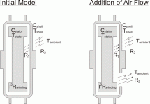
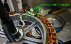
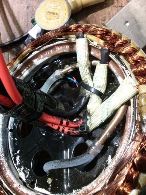
One idea I've been bouncing around is simply filling the gap between the windings and the shell with some heat conducting material. If you look at Justin's thermal model, the air between the stator and shell has the majority of the thermal resistance in the path. If we could reduce the path length to the minumum practial (clearance to avoid rubbing) and maximize the surface area of this gap, it may be possible to greatly increase the dissipation and still have a sealed system.

Oil works well because it replaces high thermal resistance air with much lower resistance oil. If the air gap between stator and shell was reduced to 2mm, the thermal resistance would be greatly reduced. The gap between the iron and magnets is already in this ballpark, so is probably the primary path for heat in a sealed hub motor. The iron and magnets don't have the best heat conductivity, but way better than air. If we added thermally conductive "filling" between the windings and the sides of the shell, leaving just a 1-2mm gap, the overall thermal resistance from copper to ambient would be greatly reduced.
From the engineering toolbox: http://www.engineeringtoolbox.com/thermal-conductivity-d_429.html
Air has a thermal resistance of 0.024 W/(m K)
Copper is 401 (16700 x air)
Aluminum is 205 (8500 x air)
Iron is 80 (3300 x air)
Magnet material 6.5 (270 x air)
Epoxy is 0.35 (14.6 x air)
Silicone oil is 0.1 (4.2 x air)
Fourier's Law are used to express conductive heat transfer
q = k A dT / s
where
q = heat transfer (W, J/s, Btu/hr)
A = heat transfer area (m2, ft2)
k = thermal conductivity of the material (W/m K or W/m oC, Btu/(hr oF ft2/ft))
dT = temperature difference across the material (K or oC, oF)
s = material thickness (m, ft)
This formula applies to a solid or non-moving fluid condition. When the motor is moving, the air (or oil) will be moving, so the thermal resistance of that path will be less.
What stood out to me is how poor a thermal conductor the magnet material is. Silicone oil is not so great either when it's not moving.
So I might try filling in the space bewteen the copper windings and the motor shell with some epoxy that's filled with powdered copper or aluminum. If I make a 2mm spacer from polyethylene or silicone rubber sheet (something epoxy won't stick to) and place it against the inside of the shell, I can fill the gap with the epoxy stuff and assemble the side and wait for the epoxy to harden. Once cured, I can remove the spacer and have a nice even 2mm gap. Repeat on the other side.
This approach would be help even with an oil cooled setup (and require way less oil).
I don't think you could apply this easily to a geared hub motor.


