Definitive Tests on the Heating and Cooling of Hub Motors

John. You need to prove your efficiency with some accurate lab equipment not just a seat of the pants feel for it and putting youre hand on the side of the motor after a ride.
As well as you increase the current in any motor the efficiency lowers. So even if you have a 90% efficient motor at 1kw its a lot less at 5kw and even less efficient at 10kw etc. Provided the pack voltage was the same for all tests.
What Justin is doing here is great because it allows people to buy motors rated for less wattage and run them with more wattage without hurting them. This is a cost and weight and energy savings at the end.
 
1+ Arlo.
John maybe you can ship a motor to undergo the same testing as all the other motors in the simulator? Would be great for people to see and simulate different setups and use for you monster motors as well. Plus that would be the proof of the pudding and there would be no more debates and hear say about it.
 
Arlo1 said:
What Justin is doing here is great because it allows people to buy motors rated for less wattage and run them with more wattage without hurting them. This is a cost and weight and energy savings at the end.

Just to be really clear about my intentions here. I named this thread "definitive tests on the heating and cooling of hub motors" with a goal not of necessarily making hub motors perform better (though that would be a nice offshoot), but more to understand the exact heat dissipating characteristics of existing popular motors so that we can have an accurate thermal model of them, and also quantify the effects of various techniques that could improve the thermal envelope. What this is all going to culminate in you can see in an early development state here:

http://www.ebikes.ca/tools/trip-simulator.html
TripSimulatorPreview.jpg

Right click on the top graph to add data points to the elevation profile, double click to remove them, left click the bottom graph to set the cursor position, and right click and drag the bottom graph to create section statistics. With a few tests in the wind tunnel on some representative hubs and then an extrapolation based on surface areas and motor core / shell weights to all the other motors, I should be able to have almost all the hub motors on our motor similutor similarly available for this trip simulation tool above.

John is totally correct that if you were designing an EV system from the ground up you can easily produce required power levels with high efficiency and not an excessive motor weight, but that's gonna require gearing from the motor to the wheel. There are a lot of reasons why direct drive hub motors are exceedingly popular and desirable, and will continue to be so even if the efficiency at high loads encountered on steep hills etc. isn't all that great. And for people using those systems, I want to produce a tool that as accurately as possible will predict the usable working envelope under any kind of terrain and load situation.

There have been a few posts to the effect of "why are you wasting your time on all of this... there's already a solution" but I'm not trying to solve a problem. Hub motors aren't a problem, they're awesome, but like everything they have their limitations, and I really want to understand and map that out to the fullest extent that we can.
 
Arlo1,

Measurements have been taken and the results computed in Miles spreadsheet. Only the foolish increase current with no increase in rpm, an all too common approach that results in ESers melting their motors. The route to higher power is not through increased current and your statements wrt efficiency and power are without merit. The factory runs the main motor I use at 7kw input, and my much lighter load enabled me to run at 16kw peak input in stock form at stock gearing without heat problems at the same voltage, because I spent so little time during acceleration. That was for 9 months, and then for nearly 2 years I ran it at 50% higher voltage, but ventilated and bumped the current up a bit for 27kw peak input, and have a much cooler motor despite the stock gearing (wheel size). At a reduced gearing, the efficiency range would broaden to include lower speeds, and if I combine that with increased voltage, the motor is easily capable of 35kw+ input with a very broad range of 90%+ efficiency.

My own usage only proved that the manufacturer's claims were reasonable. Feeling temps by hand is something from years ago that I did to learn how to avoid heat problems with more common designed motors I used to use. The 94-95% peak efficiency claimed by the manufacturer, I've proven in real world conditions for over 3 years now put the motors in a totally different class than motors people commonly use. If people don't want to use their grey matter to put them to work on their bikes is their loss.

Your attitude is fine with me, because soon I won't even offer the motors for sale. Instead I'll make packaged solutions available that include margins worthy of my efforts, though they'll still have the best performance/dollar ratio by a long shot. I'm the only vendor of high performance motors who uses a very conservative approach to claims, and who approaches EVs with the idea that they should be cheap. I find your inaccurate statements offensive, as well as unfair considering that I'm held to a higher standard than anyone else, especially since I'm the only one meeting and exceeding those standards.

John

Arlo1 said:
John. You need to prove your efficiency with some accurate lab equipment not just a seat of the pants feel for it and putting youre hand on the side of the motor after a ride.
As well as you increase the current in any motor the efficiency lowers. So even if you have a 90% efficient motor at 1kw its a lot less at 5kw and even less efficient at 10kw etc. Provided the pack voltage was the same for all tests.
What Justin is doing here is great because it allows people to buy motors rated for less wattage and run them with more wattage without hurting them. This is a cost and weight and energy savings at the end.
 
macribs said:
1+ Arlo.
John maybe you can ship a motor to undergo the same testing as all the other motors in the simulator? Would be great for people to see and simulate different setups and use for you monster motors as well. Plus that would be the proof of the pudding and there would be no more debates and hear say about it.

Use Miles spreadsheet to learn about the operation of motors and the proof is already contained therein. There is no debate or hearsay other than from naysayers. My motors have more copper per unit of torque for less copper losses, and a lower pole count and expensive Japanese lamination steel for less iron core losses than cheaply made common hubbies. It's as simple as that. There may some side benefits related torque ripple that may be part of what makes them more quiet and have a tiny impact on efficiency, or it could come from the simple fact that that halls are shielded, but no claims about that have ever been made.
 
justin_le said:
fechter said:
How about if the stator had concentric 'fins' along the sides and they intermeshed with fins on the inside of the covers.

Funny that was also just the picture I was envisioning in my head too. Without doing FEA models of the air flow it's hard to say what precise benefits might or might not come from clever inter-meshing fins but it's hard not to imagine this having a positive effect. If we could get the overall heat transfer from stator to side plates some 2-3 times better than it is by at current with _zero_ design optimizations, then that would be almost as good as an oil fill solution.

The main barrier to heat flow at that point becomes the side plates to ambient. Some wind tunnel tests coming fairly soon to quantify/characterize that.

-Justin

That's what I was thinking. Putting some fins on both sides of the housing won't add that much to the manufacturing cost.
I'm sure there are some very detailed analyses of heat transfer from a chunk of aluminum to air. I'm sure there are programs to optimize the geometry of the fins as well. What I don't know is what happens in the case of two moving chunks separated by a small air gap. I know from experience that increasing the air flow greatly increases the heat dissipation ability.
 
justin_le said:
Hub motors aren't a problem, they're awesome, but like everything they have their limitations, and I really want to understand and map that out to the fullest extent that we can.

+1 Justin, and I apologize for off topic stuff I post. I just always feel compelled to answer their BS attacks. I wish I could stay above the fray like you.

BTW, I've consulted with my manufacturer after they saw the power levels I was running their motors, and together we believe they can run conservatively 30% higher power at the same operating temps with a dry sealed approach with the primary changes being doubling the surface area inside and out that will also increase flow velocity over the surfaces. Those changes combined with a slightly narrower stator and more bike friendly shell and axle could easily result in a DD hubbie for ebikes capable of real efficiency in the low 90's.

Hopefully at some point this discussion turns from more rapidly rejecting heat to making less heat to begin with. I see that there's much more to gain in that direction even with common high 80's peak efficiency hubbies. That's because the general rule is run DD hubbies in wheels that are too big, push current too high, and use battery/phase ratios that are only applicable for 1000W or less.
 
fechter said:
justin_le said:
fechter said:
How about if the stator had concentric 'fins' along the sides and they intermeshed with fins on the inside of the covers.

Funny that was also just the picture I was envisioning in my head too. Without doing FEA models of the air flow it's hard to say what precise benefits might or might not come from clever inter-meshing fins but it's hard not to imagine this having a positive effect. If we could get the overall heat transfer from stator to side plates some 2-3 times better than it is by at current with _zero_ design optimizations, then that would be almost as good as an oil fill solution.

The main barrier to heat flow at that point becomes the side plates to ambient. Some wind tunnel tests coming fairly soon to quantify/characterize that.

-Justin

That's what I was thinking. Putting some fins on both sides of the housing won't add that much to the manufacturing cost.
I'm sure there are some very detailed analyses of heat transfer from a chunk of aluminum to air. I'm sure there are programs to optimize the geometry of the fins as well. What I don't know is what happens in the case of two moving chunks separated by a small air gap. I know from experience that increasing the air flow greatly increases the heat dissipation ability.

My issue with concentric circles is twofold:
1. It doesn't lead to increased flow velocity toward the perimeter like axial veins can making them also more prone to buildup of dirt and road grime, which is counter productive.
2. They decrease the overall structural strength of the side cover. If done radially even channels that cut almost all the way into the side covers could have less effect on structural integrity, and vanes would be only additive in terms of strength.
 
John in CR said:
macribs said:
1+ Arlo.
John maybe you can ship a motor to undergo the same testing as all the other motors in the simulator? Would be great for people to see and simulate different setups and use for you monster motors as well. Plus that would be the proof of the pudding and there would be no more debates and hear say about it.

Use Miles spreadsheet to learn about the operation of motors and the proof is already contained therein. There is no debate or hearsay other than from naysayers. My motors have more copper per unit of torque for less copper losses, and a lower pole count for less iron core losses than cheaply made common hubbies. It's as simple as that. There may some side benefits related torque ripple that may be part of what makes them more quiet and have a tiny impact on efficiency, or it could come from the simple fact that that halls are shielded, but no claims about that have ever been made.


Sorry John I was not trying to make it out like you make invalid claims about your motors - not by a longshot. If it came out that way I am truly sorry. As a non-native english speaker communication in English can be a challenge, sometimes it is hard to express what you intend to say in english so that other people read it the way it was intended.

John I've read your posts and seen what those motors are capable of so there is no doubt in my mind they are great motors. What I tried to point out is that it would be nice for people getting into e-bikes to be able to see your motors in the same simulator to let them make better informed choices. In fact I think you should view that simulator as a chance and opportunity to further expand the word of your dual 3 phase motors. So that more people would see how they perform. The fact that you can achieve higher power using 2 lower spec'ed controllers with your motors then people sinking twice or three times as much money into just 1 controller/hub and they still do not see peak power past 15 kw, that really should be in the simulator - it would be an asset to the community and I am sure in the end it would drive even more customers and business your way.

You reach peak power is 27 kw with your dual 3 phase motor with venting holes. People putting down twice the money for other motor/controller combos still need to spend a lot of time (and also extra cash) modifying their hubs to safely get half of the peak power your 6 phase motor is reaching. 27 kw that is impressive.

While your motor will not fit everyones needs that is all fine, choices and alternatives are good. But is also important to have enough information to make the right choice - hence the 6 phase in the simulator. Just one mans thoughts.

If that motor could be scaled down a bit, say peak at 20 kw and made a little smaller, a little thinner it would make it even easier for people to use the 6 phase motor in various builds.
 
Macribs,

Both models are listed with full data in Miles' motor comparison spreadsheet, so you can get to any raw motor performance info you want. They're not ebike hubbies and really don't belong on an ebike simulator anyway. Cromotor and Markcycle's motorcycle hubmotor aren't listed in the simulator or Miles' motor spreadsheet either, but no one is pushing to get them listed.

Profit is not my motive to sell the motors, and the tiny margin hasn't even paid for my test motors, so the expectation that I should incur the cost to send a motor to put in an ebike simulator isn't reasonable.

Hillsofvalp put his on a dyno and got almost 21kw at the wheel with voltage at 75V. Hopefully LiveForPhysics will run a higher voltage and avoid Hillsofvalp's mistake of running current too high. That's the route to high power and high efficiency.
 
John in CR said:
Macribs,

Both models are listed with full data in Miles' motor comparison spreadsheet, so you can get to any raw motor performance info you want. They're not ebike hubbies and really don't belong on an ebike simulator anyway. Cromotor and Markcycle's motorcycle hubmotor aren't listed in the simulator or Miles' motor spreadsheet either, but no one is pushing to get them listed.

Profit is not my motive to sell the motors, and the tiny margin hasn't even paid for my test motors, so the expectation that I should incur the cost to send a motor to put in an ebike simulator isn't reasonable.

Hillsofvalp put his on a dyno and got almost 21kw at the wheel with voltage at 75V. Hopefully LiveForPhysics will run a higher voltage and avoid Hillsofvalp's mistake of running current too high. That's the route to high power and high efficiency.

I understand John, there is a financial outlay to have the tests completed, in form of motor and shipping. And that is why we tried to push for getting together community funding for testing either the cromotor or the QS 205 v3 earlier this year. I think we only manged to get 5-6 people that was willing to donate cash to have those motors. If in the future we can rally up more backers to help pay for motors we could also try to take collect to have your hubmonster included. That way the costs for the the hardware would be on the community.
 
John in CR said:
My issue with concentric circles is twofold:
1. It doesn't lead to increased flow velocity toward the perimeter like axial veins can making them also more prone to buildup of dirt and road grime, which is counter productive.
2. They decrease the overall structural strength of the side cover. If done radially even channels that cut almost all the way into the side covers could have less effect on structural integrity, and vanes would be only additive in terms of strength.

I agree radial fins would be better on the outside. Concentric rings on the inside that intermesh with rings on the stator would probably give better heat transfer.

I also agree that generating less heat in the first place would be a much better approach if possible. Where's that graphene wire?
 
why fins not pins... why not just drilling and threading some holes on the sides and screw some copper screws from the Inside to outside, ... and make your hub looking like a sea urchin :D

0bafe458-18f0-43e4-b8cd-74236b4d35ca.jpg
 
made_in_the_alps_legacy said:
why fins not pins... why not just drilling and threading some holes on the sides and screw some copper screws from the Inside to outside, ... and make your hub looking like a sea urchin :D

That's an idea I almost pulled the trigger on, though I was going to use aluminum bolts. I wanted to at least find out how much windage it added before deciding whether I could live with the look, though organizing the bolts in an interesting pattern would help.
 
fechter said:
Concentric rings on the inside that intermesh with rings on the stator would probably give better heat transfer.

Now I see where you're going....Interesting idea. Adding surface area to the stator and both sides of the covers will definitely increase heat transfer. I stick with simple, so I'll leave that one to you.
 
It still will have a air boundary layer that is very poor at heat transfer. Other than a redesign, liquid/mass coupling or straight up venting seem to be the most promising for significant cooling. Noticed some good looking large bearings on VXB site that could have some potential in a core hub/axle redesign. 80mm ID for under $65. Plenty or room for tubes /pipes and wires.
6816-2rs-1.jpg


Still thinking a stationary left side shared cover-core support with a labyrinth type seal and a single side rotor support maybe the best in a green field redesign from a cooling standpoint. I see several single side mount hub motors in scooters but found none yet with a large solid stationary sideplate- core mount.
 
The copper bolts are interesting. For the distance involved, the aluminum covers are probably just as good.
I need to do a bit more research on what's happening in that boundary layer. I know intuitively that more air velocity increases heat transfer. There may be some limit to that.

Heat pipes are another interesting technology that could possibly be useful. I don't think running a heat pipe through the axle would be practical though.

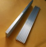
I've seen some nice, inexpensive extruded aluminum heat sink fins on eBay. Some look to be thin enough to bend into a curve that matches the inside of a stator. Would also fit on the outside of the housing in the space between the spokes. These could be attached with metal-filled epoxy or just silicone RTV if the gap is thin.

These are 6mm thick:

Heat Sink.jpg
 
It seems more like a job for those aluminum brazing rods to install blades instead of trying to fit heat sinks to a compound curve.
 
I spend a couple of hours reviewing scholarly articles on heat transfer in rotating machines. This is a very well studied issue.
My head is still spinning from all the partial differential equations, but a few tidbits did rise to the top. One is that about 90% of the heat transfer between rotor and stator occurs in the air gap (the space between the magnets and the stator iron). In a rotating machine, the heat transfer was approximately inversely proportional to the gap distance. Heat transfer increases dramatically as the flow transitions from laminar to turbulent. Increasing the 'roughness' of the surfaces promotes turbulent flow. In a direct drive hub motor, I don't think it will ever spin fast enough to be really turbulent. The primary mode of heat transfer is through convection, but radiation is also a significant factor (maybe 15% of the total).

A few things to try:
1. paint the insides of the covers, magnets and stator with flat black paint to enhance radiation.
2. increase the roughness of the magnet and stator surfaces (not exactly sure the best way to do this). The stator is already pretty rough due to the teeth.
3. fill the space between the ends of the windings and the side covers so there is a small gap. This increases the gap area.

Forced-air cooling has an additional set of factors the primary being air velocity over the surface and the surface area. The goal is to get the flow into the turbulent region. I'm concentrating on solutions that don't involve adding pumps, blowers, etc. for simplicity. Obviously water or oil cooling is going to be better, but the additional complexity should be avoided.

Another interesting idea I ran across was filling the gap with ferrofluid. Not only does it transfer the heat better, but also increases the flux density in the gap.
 
Hm ferrofluid you say. Interesting. Are there various qualities of ferrofluid or various viscose's? When I searched the forum for ferrofluid I see it mentioned briefly 5-6 years ago, does not appear any was biting.

wikipedia said:
An external magnetic field imposed on a ferrofluid with varying susceptibility (e.g., because of a temperature gradient) results in a nonuniform magnetic body force, which leads to a form of heat transfer called thermomagnetic convection. This form of heat transfer can be useful when conventional convection heat transfer is inadequate; e.g., in miniature microscale devices or under reduced gravity conditions.

Ferrofluids are commonly used in loudspeakers to remove heat from the voice coil, and to passively damp the movement of the cone. They reside in what would normally be the air gap around the voice coil, held in place by the speaker's magnet. Since ferrofluids are paramagnetic, they obey Curie's law and thus become less magnetic at higher temperatures. A strong magnet placed near the voice coil (which produces heat) will attract cold ferrofluid more than hot ferrofluid thus forcing the heated ferrofluid away from the electric voice coil and toward a heat sink. This is an efficient cooling method which requires no additional energy input.[12]

Ferrofluids of suitable composition can exhibit extremely large enhancement in thermal conductivity (k; ~300% of the base fluid thermal conductivity). The large enhancement in k is due to the efficient transport of heat through percolating nanoparticle paths. Special magnetic nanofluids with tunable thermal conductivity to viscosity ratio can be used as multifunctional ‘smart materials’ that can remove heat and also arrest vibrations (damper). Such fluids may find applications in microfluidic devices and microelectromechanical systems (MEMS).[13]

Ferroflid how it works:
[youtube]PvtUt02zVAs[/youtube]

Ferrofluid
[youtube]D2j2YmPxZX0[/youtube]
 
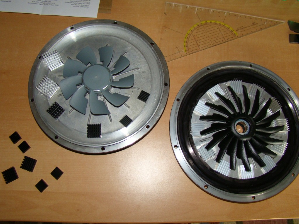
ordered some different sized heat sinks for inside installation:

ULM78q.jpg


my plan: the cover on the right i will place on chain side. the grey blower wheel and the silver pinned heat sinks i will place on brake side. im going to cut them in half so i can stick them between the stiffeners/fins on the cover. from the grey blower wheel i will remove 6 blades so it is a 3 blade and those cut pinned heatsinks i will place between the remaining 3 blades.
the blower wheel fits exactly on the bearing flange on the sidecovers which makes installation very easy.
 
fechter said:
I spend a couple of hours reviewing scholarly articles on heat transfer in rotating machines. This is a very well studied issue.
My head is still spinning from all the partial differential equations, but a few tidbits did rise to the top. One is that about 90% of the heat transfer between rotor and stator occurs in the air gap (the space between the magnets and the stator iron). In a rotating machine, the heat transfer was approximately inversely proportional to the gap distance.

Hi Fetcher, you wouldn't happen to still have the reference handy which showed this result? It would have direct ramification on the concentric stator->side cover fins idea. I also found some interesting academic papers covering the convective heat transfer between a rotating and a stationary disk, which is much like what we are trying to achieve in transferring heat from stator core to the side plates, though I wasn't able to fully digest it. A ton of interesting patents on the subject of motor cooling too of course, and one that I loved suggested using heat pipes as the copper winding material. Talk about nipping the heat right at the source.


Another interesting idea I ran across was filling the gap with ferrofluid. Not only does it transfer the heat better, but also increases the flux density in the gap.

I followed your other thread about this, it's a pretty "out there" idea, although it seemed to imply that it had a negative effect on the motor performance on hubs with a thin air gap (like hub motors), and the flux density improvement was only notable when there was a fairly large air gap to span. But I like it as a really cool way to have oil cooling in a way that keeps the oil stuck around the rotor magnets and not leaking out the bearings, wire harness etc. A slow-mo video from a camera inside the motor looking at the liquid ferrofluid react to the changing fields of a spinning motor, I'd pay to see that.

made_in_the_alps_legacy said:
why fins not pins... why not just drilling and threading some holes on the sides and screw some copper screws from the Inside to outside, ... and make your hub looking like a sea urchin :D

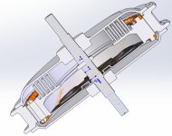
Well I think all we really need is something on the inside, and yeah circles of pin-like protrusions would possibly be more effective and certainly less weight. For those who haven't been following this too closely, for me this is one of the most exciting prospects for more effective motor cooling that I've heard discussed and I'm really stoked to do some tests on this front. The basic idea is to massively increase the surface area and proximity between the stator heat mass and the side cover heat mass with closely spaced interleaved fines like so:
HeatFins Idea.jpg

This should largely increase both the convective transfer and the radiative transfer, and if as Fetcher says the effective heat transfer between concentric cylinders is largely inverse to the gap distance, then with numerous thin gaps we could perhaps get quite a significant coupling.
 
justin_le said:
A slow-mo video from a camera inside the motor looking at the liquid ferrofluid react to the changing fields of a spinning motor, I'd pay to see that.
Plex/lexan/etc side cover.... ;)
 
I liked the idea of having your copper fill be the heat pipes! That is Bruce Lee wisdom. (Become the water...)

Has anyone try to quantify how much heat is removed via the phase wires? And how much heating of the outside phase wires do people see? Is the temp rise noticeable at all? What if the phase's was laid into machined grooves in a heat sink placed on the swing arm? Here the placement would be easy, the added real estate would not matter, and heat sink could be as large as needed.

But it only makes sense to go this route if there is some quantified data about how much heat is dissipated via phase wire.
 
amberwolf said:
justin_le said:
A slow-mo video from a camera inside the motor looking at the liquid ferrofluid react to the changing fields of a spinning motor, I'd pay to see that.
Plex/lexan/etc side cover.... ;)

Yes and a gatro cam inside the hub. Would make for a block buster ;) at elast on ES.
 
Back
Top