EM-100 knockoff queries

Blackgolem

10 µW
Joined
Sep 6, 2023
Messages
5
Location
Canton Ohio
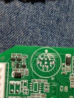
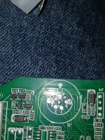
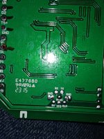
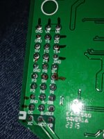
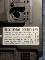
Hello everybody right into it. I bought a em-100 80a controller it says voltage range is 60-72v. I've notice the surron controller has 2 green wires connected switch from 60 to 72 and this don't. Looking at my photos can anyone point me to area to connect that. Also I see a round 8 pin area is that for a programable dongle to hook up? Any help folks is appreciated good or bad.20231017_155804.jpg20231017_155707.jpg20231017_155643.jpg20231017_155542.jpg20231017_155440.jpg
 
Hello everybody right into it. I bought a em-100 80a controller it says voltage range is 60-72v. I've notice the surron controller has 2 green wires connected switch from 60 to 72 and this don't. Looking at my photos can anyone point me to area to connect that. Also I see a round 8 pin area is that for a programable dongle to hook up? Any help folks is appreciated good or bad.View attachment 341426View attachment 341427View attachment 341428View attachment 341429View attachment 341430
Okay so I must need to see my own questions to find answers 🤔 and doing the research I will have it posted here. So what I've found so far is that at the 8 pin connector the RX: = the receiver pin of the dongle, TX:= the transmitter pin, CLK:= trigger pulse signal and if I understand that's like to say OK now. DIO: digital in and out. NTSC: communications pin. I am speculating now but it appears 5v activates the board TX transmits the board interface RX receives the program from etc. All I have to do is connect? Let me know if on the right track
 
If you look at where the traces from the pins in question go, they seem to unpopulated parts pads. if so, then wiring things to the pins wont' help; you'd also need to find out what parts go in those unpopulated pads and install them.

Also, it's possible the firmware on this controller doesn't even support programming, switches, etc., if it doesn't have the parts installed to connect to them.
Thanks amberwolf saves me a lot of headache will this controller auto detect voltage applied perhaps I mean it doesn't have the green wires that switches to 72v and could 80a mean it's limitations so below 80a is workable from your perspective? I know its off topic but if you'll set me straight
 
i have no way of knowing what your specific controller will do (you'd have to check it's manual if there is one available for it, since if it's not a genuine Votol it may not behave the same), but there *are* autodetecting controllers out there. They work by detecting the voltage as they turn on, so if you have a nearly empty battery pack of the higher voltage, sometimes they goof up and detect it as the lower voltage pack, and vice-versa.

For non-auto controllers, the controller's LVC is simply set to the lower voltage's LVC, so when you use it with a higher voltage battery it won't shutdown to protect an empty battery, so the battery's BMS has to be the only layer of protection (it's supposed to be the last emergency layer).

As for the current limit, it means that it shouldn't draw any more than 80A from your battery under max load. So your battery needs to be able to easily supply 80A. If it can't, it will either be overstressed, and sag in voltage more than it should, and heat up, or the BMS will shutdown it's output, etc.
 
i have no way of knowing what your specific controller will do (you'd have to check it's manual if there is one available for it, since if it's not a genuine Votol it may not behave the same), but there *are* autodetecting controllers out there. They work by detecting the voltage as they turn on, so if you have a nearly empty battery pack of the higher voltage, sometimes they goof up and detect it as the lower voltage pack, and vice-versa.

As for the current limit, it means that it shouldn't draw any more than 80A from your battery under max load. So your battery needs to be able to easily supply 80A. If it can't, it will either be overstressed, and sag in voltage more than it should, and heat up, or the BMS will shutdown it's output, etc.
Very knowledgeable amberwolf thanks for not stringing me along. I actually thought likewise on all issues of this controller and being as it will be used with a 20s6p battery pack using 2.5ah cells with 7a discharge planning to add 4 more parallel rows. I'm thinking I could get at least 100a from it but only going to use a 60a bms that should help my cells right? On my other build I have a 52v battery same cells when checking phase current on throttling up my 20° hill I draw a 100a for split second.I will give it a shot and pray for the best thanks sir for your assistance.
 
. I actually thought likewise on all issues of this controller and being as it will be used with a 20s6p battery pack using 2.5ah cells with 7a discharge planning to add 4 more parallel rows. I'm thinking I could get at least 100a from it but only going to use a 60a bms that should help my cells right? On my other build I have a 52v battery same cells when checking phase current on throttling up my 20° hill I draw a 100a for split second.I will give it a shot and pray for the best thanks sir for your assistance.
If you use a 60A BMS but an 80A controller, the system is going to turn itself off whenever you have a high enough load on the motor from the riding conditions you have (like the hill).

If the BMS is not just 60A for a current limit, but can only handle 60A max, then it will fail, blowing up the FETs.

Your battery has to be *more capable* than the controller. If it is *less capable* it cannot run the system correctly, and will either be stressed (or even damaged), or shutdown the whole system when the need is higher than the battery can supply.

If each cell is capable of a *max* of 7A, then to handle 80A you require *at least* 12 parallel cells in each group. More would be better, so the pack is less stressed, has less heating, and less voltage sag, so you get more watts at the wheel instead of wasting them as heat in the battery and aging it faster.

So you need *at least* two batteries like you already have, because at 7A per cell x 6 cells that's only 42A, and you *must* be able to supply *at least* 80A to meet the controller's needs.

If the 7A is a max peak or burst current (peak or burst is a few seconds, infrequently), then you need an even bigger battery pack, since it needs to be able to *continuously* supply the max current the controller will draw (like on that hill). You'd need to find the *continuous* current spec for the cells, and use that to figure out what the battery has to be to do what you want.


If you want to protect your cells with a BMS, then as-is with a 6p pack, you need a 40A BMS or lower, assuming the 7A is continuous and not max/peak. With a 10p pack, the 60A BMS would protect that. But neither one will supply what your controller needs whenever it is loaded to it's limit.
 
So in short 20s12p = 2 20s6p basically combined. My math was wrong then because I was thinking ignorantly that I was measuring amps via the string of 20 cells you know coming up with amps I wanted
 
Back
Top