
You are using an out of date browser. It may not display this or other websites correctly.
You should upgrade or use an alternative browser.
You should upgrade or use an alternative browser.
Hardware temperature control tsdz2
- Thread starter andrea_104kg
- Start date
Piper j3 , I don't want to be a false prophet but inlet is too small to work and corrugated pipe makes great friction for air to flow fast ... nevertheless I'm curious but sadly I think it won't work as expected . I think it's better to fill motor case with aluminium or copper and transfer heat to outer shell . I think there is market for someone who would machine tight case with massive radiators from aluminium and sell it .
on the other hand is this design flaw forced by ebike regulation that it has to overheat after certain time under certain power ?
on the other hand is this design flaw forced by ebike regulation that it has to overheat after certain time under certain power ?
ornias
100 W
- Joined
- Jul 18, 2021
- Messages
- 172
pxl666 said:on the other hand is this design flaw forced by ebike regulation that it has to overheat after certain time under certain power ?
Cannot say for sure, ofcoarse, but if the cooling would be much better I fear it indeed wouldn't have passed EN15194 certification.
Mostly because that electromotor is actually pretty good stuff!
I have OSF motor limit set to 450W and also 12A max from 48V battery. This in itself should limit heat buildup. I ride very efficiently and choose low gearing so motor doesn’t work so hard.
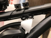
I’m going to add a “funnel” to the inlet air tube which will make ram air like a hood scoop on a 70’s muscle car. The corrugated tube should be sufficient diameter and short enough not to cause too much air restriction.
What I’m trying to achieve is a moderate air exchange in the motor housing. There should be some temperature improvement with flowing ambient air Vs. stagnated air at ~ 180F. Also, if motor does get hot, the incoming air should allow it to cool quicker than convection heat transfer through non-moving air.
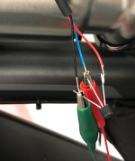
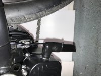
from how the pipes are organised it could happen that when stationary the hot air will be pushed upward. If you persist to face inlet forward i would lower the intake i order to avoid any small particles falling inside motor housing, so build kind of syphon. It could actually also work if the uppper pipe would face rearward as exaustPiper J3 said:Done…. My attempt at air-cooling the TSDZ2 motor is complete. I still need to get LM35 temp sensing working. I will add a temporary two-channel temp sensor for inlet and exhaust air temps to gather data. Unfortunately… testing won’t happen for several months. Weather is too cold for my 70-year-old bones.
-
Change of plans…. Per the TSDZ2 Temperature Sensor LM35 Issues Thread https://endless-sphere.com/forums/viewtopic.php?t=113286, the OSF version I’m running has a code problem that inhibits temp display above 62.4C. I don’t have a cable, or ability, to flash new code when its available. Instead, I will buy these temp sensors on Amazon…. https://www.amazon.com/gp/product/B01MRR4HGM/ref=ppx_yo_dt_b_asin_title_o00_s00?ie=UTF8&psc=1 Cost is $10 for 5 units, so almost free... I will then measure inlet air temp, motor temp, and outlet air temp. I’ll mount three of these units temporarily just to get data and prove / disprove air cooling of the TSDZ2. Once I get a handle on air cooling, I’ll remove the temperature sensors and just ride bike like a normal human being…. 
You aren't running v20.1C.2 (or lower) for stock displays (XH18, Vlcd5, Vlcd6).Piper J3 said:Change of plans…. Per the TSDZ2 Temperature Sensor LM35 Issues Thread https://endless-sphere.com/forums/viewtopic.php?t=113286, the OSF version I’m running has a code problem that inhibits temp display above 62.4C. ..... Instead, I will buy these temp sensors on Amazon....
You have an 860C display, that is not stock.
Because you haven't the ability, to flash new firmware, I suspect you ordered a set with flashed OSF from Eco Cycles.
As mbrusa said, than you shouldn't have this problem.
Also 62.4 isn't the same as your 66.
Imho your problem is another one. Problably fake LM35
But using the sensors from Amazon is ofcourse the most easy solution in this case
So, I have 860C with 0.20.1c-4 and TSDZ2 with 0.21.4. I ordered Texas Instruments LM35DZ which should be good quality. I plan to test first on bench at 5VDC. Do you think LM35 will work correctly and show complete temperature scale with firmware I’m running?
Imho, Yes (if nothing is broken with the fakes)Piper J3 said:... 860C with 0.20.1c-4 and TSDZ2 with 0.21.4. .... Do you think LM35 will work correctly and show complete temperature scale with firmware I’m running?
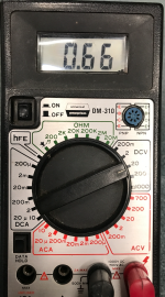
I received temperature sensor from Mouser and powered it on the bench at 7V. The sensor lead is showing 0.66 which is close to room temp. I heat the sensor with a hot-air tool and sensor goes up scale nicely.
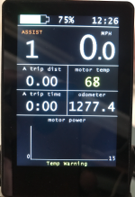
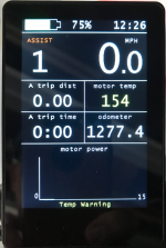
I then connected the sensor to the TSDZ2 controller for a quick check using the throttle connection at the 1-4 cable. Power at the cable supplied from the TSDZ2 controller is 4.32V and sensor lead still shows 0.66 on the VOM. So, all should be good except the 860C display shows 154 when set to F and 68 when set to C. Both values are in red color. I changed Motor Temp min and max limits and it doesn’t fix problem.
I’m wondering if OSF is looking for a centigrade value from the sensor instead of Fahrenheit….
Attachments
Ofcourse, the output of LM35 should be 10mV/K = 10mV/°C . For 100°C would be measured 1.00VPiper J3 said:....
I’m wondering if OSF is looking for a centigrade value from the sensor instead of Fahrenheit….
Measuring 0,66V would be 66°C or 151°F which isn't quite room temperature. :wink:
So it looks that these sensors also aren't correct.
I ordered LM35DZ from Mouser and they sent me SEN-10988 which is a TMP36. All the LM35 I ordered from Amazon appear shorted and get hot when connected to 6V. The new TMP36's (qty -5) all seem to work, but output F instead of C per spec. I called Mouser tech support and they don't have explanation. TSDZ2 OSF is looking for temp in C, so my displayed value is way too high.
TMP36 is also for measuring °C, but the output is different from LM35.Piper J3 said:.... TMP36. .... output F instead of C per spec. ....
0.1V (-40°C) to 2.0V (150°C)
Measuring 0,66V is (660-500)/10 = 16°C or 61°F
It just looks TMP36 measures Fahrenheit with 0.66V measured value, but isn't.
If I was you, buy the cheap thermometers with display.Piper J3 said:Problem is no stock for LM35DZ from reputable distributors. ....
There doesn’t appear to be any LM35DZ available at reputable distributors. I’m now thinking about Mouser TMP35GT9Z which has correct 10 mV/°C scale factor . Temperature range is 10C to 125C so the lowest temp displayed will be 50F... that’s not a problem. Operating voltage is 2.7 V to 5.5 V which will work with available 4.3V at the TSDZ2. Spec sheet suggests filtering capacitor so, I'll get a 0.1uF and a 10uF capacitor to filter both low and high frequencies at the motor.
I don’t give up easily….
I don’t give up easily….
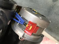
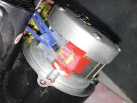
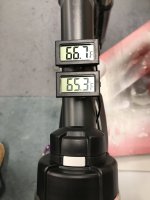
New TMP35GT9Z temperature sensor arrived today. Works perfectly. Correlates well with two stand-alone temp sensors that I’ll use to measure motor housing inlet and exhaust air. Still need to clean up wiring and add filter capacitors.
Also need to set temps for motor inhibit, but so far, looks like bike is on a good path….
-
Also need to set temps for motor inhibit, but so far, looks like bike is on a good path….
-
Attachments
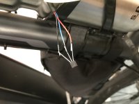
I finished installation of the TMP35GT9Z with filter capacitors. Very good correlation to sensors I will use to measure inlet and exhaust air temp at the motor housing. Last thing to work on is the ram air “scoop” which should provide a positive pressure in the inlet hose and a moderate air flow through the motor housing...
Attachments
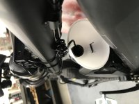
I used a 3” plastic funnel for a ram-air “scoop” which should provide a positive pressure in the inlet hose and a modest air flow through the motor housing. Temporary sensors will monitor inlet and exhaust air temperatures. If data shows a cooling trend, I’ll make a ram-air inlet that is more aesthetically pleasing. I will test ride as weather conditions allow. Final evaluation will need to be done in the heat of next summer. Fun project….
Attachments
I do not believe this will be precise measurement. just do a test run without system and measure temperature or just note how long to reach a cut off temp ,and then try with system .
the problem is mostly noticeable while hard climbing in mtb conditions . the speed is low and there is very little air movement. and motor is pushed to the limit.
the problem is mostly noticeable while hard climbing in mtb conditions . the speed is low and there is very little air movement. and motor is pushed to the limit.
I’ll be able to measure inlet air temp very accurately, and I think get a good handle on exhaust air temp as well. What I won’t be able to do is detect or measure air flow. Any air flow at all through the motor housing is better for cooling than a closed system. If I measure a difference in/out then the flow of air will be doing “some” cooling.
I have a second unmodified cover for the motor housing and can easily changeout on any given day for direct comparison. I’m really hoping that limiting power to 450W and 12 amps keeps motor temp in acceptable range for my style of riding….
I have a second unmodified cover for the motor housing and can easily changeout on any given day for direct comparison. I’m really hoping that limiting power to 450W and 12 amps keeps motor temp in acceptable range for my style of riding….
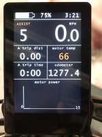
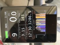
I just did a 3 mile test ride in the “hood”. Too cold to ride normal trail. Outside air temp is 43F. I used max assist power level and kept bike in higher gears to increase motor temperature. Display graph shows 450 watts for most of the ride. Motor reached a maximum temp of 145F.
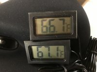
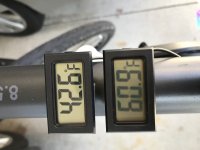
The air-cooling appears to be removing at least some heat from the motor. Inlet air temp matched 43F outside. Motor housing exhaust showed 65F during the last half of the ride. So, cool ambient air is entering the front of the housing and air heated by motor and speed controller is being exhausted at the back of the housing. I can’t do any sophisticated heat transfer calculations because I don’t now air flow. I’m just happy that some hot air is being spilled overboard.
I’ll keep the bike fully instrumented and we’ll revisit this thread in the heat of next summer…
Attachments
i wonder if anyone tried to remove cover and compared temp with and without cover on same route . this would tell how much heat stays inside and how big is the difference with airflow . alternatively i can imagine making holes in housing and cover them in case of rain

imho this is what the topicstarter Andrea_104kg did.pxl666 said:i wonder if anyone tried to remove cover and compared temp with and without cover on same route . ....
Similar threads
- Replies
- 8
- Views
- 684
- Replies
- 35
- Views
- 17,668
- Replies
- 11
- Views
- 2,216
- Replies
- 112
- Views
- 20,050