Hardware temperature control tsdz2

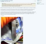
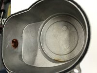
On the Italian forum Jobike I saw a clever solution (by bomen67) with 0.8mm copper "springs" around the stator.
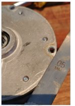
On a copper collar around the stator, he soldered some copper springs which are in contact with the case cover.
Maybe some copper spunge in between will increase the contact with the cover too.

source

2022119153311_20220522_144410a.jpg
2022119153337_20220522_144425a.jpg
 
isn't better to just cut piece of pipe of right (60mm?) diameter and fill gaps with thermal paste? or shape copper sheet of 3mm thickness ?
 
pxl666 said:
isn't better to just cut piece of pipe ......
Such a pipe must be tapered for a correct fit of the cover. If you read back, you understand what I mean.
Such copper springs arrange themselves under the cover.
 
I’m working on a simple design to air-cool the motor and controller. Concept sketch is below. Parts on order and work will commence next week. I’ll post again when job is complete….
 

Attachments

  • IMG_4591.jpeg
    IMG_4591.jpeg
    3.3 MB · Views: 584
Piper J3 said:
I’m working on a simple design to air-cool the motor and controller. Concept sketch is below. Parts on order and work will commence next week. I’ll post again when job is complete….

This is just waiting for a short circuit or burned out something due to moisture.
 
The controller is fully-potted, so moisture won't be a concern and motor is brushless, so no moving parts other than rotor. Same technology as used for Radio Control Model airplanes / helicopters where Electronic Speed Control (ESC) and brushless motor can operate in the rain. TSDZ2 will still be plenty warm and moisture will no condense...
 
Piper J3 said:
The controller is fully-potted, so moisture won't be a concern and motor is brushless, so no moving parts other than rotor. Same technology as used for Radio Control Model airplanes / helicopters where Electronic Speed Control (ESC) and brushless motor can operate in the rain. TSDZ2 will still be plenty warm and moisture will no condense...

The is open for water ingress on the backside and none of the contacts anywhere are actually potted.
Lithium battery connections of, lets say, 50v and moisture... that's not going to be a pretty sight...

The fact the motorunit itself is brushless is not very relevant tbh.

Ask yourself: "Why is no manufacturer anywhere doing this"...
The answer is: Any arking or shorts of this powerlevel kills people and actually has burned down houses. Honestly: If you think this is a safe idea, you should be prevented from trying this.

Also:
"moisture" does not mean "humidity" btw ;)
 
Piper J3 said:
The controller is fully-potted, so moisture won't be a concern..... TSDZ2 will still be plenty warm and moisture will no condense...
You could be right, but water ingress with electronics is never a good couple.
Have you contacted the TS andrea_104kg for his long term results? It could be handy before cutting holes.
He was also experimenting with airflow, but I know that he use the heatsink plate now.
 
There won’t be any water ingress to the motor case... Sealed fittings and ½” tubing will be used for decent air flow. The inlet tube will act like a snorkel. Air will be obtained high-up on the bicycle frame so air will be clean with no chance of water ingress. The inlet tube will face forward into the slipstream so a slight positive pressure is developed.

Air will exit the motor at the rear of the housing thru a vertical tube pointing down. Splash from the wheels will not enter the exit tube. The tube will have a 45-degree chamfer to create a negative pressure when bicycle is in forward motion. This same technique was used on old cars to ventilate the engine crankcase (road tube) before PCV valves were invented.

I’m sure manufacturers of mid-mount motors have water ingress as a prime design consideration and thus seal the unit. In my case, the bicycle is used only on dry roads so water ingress will never happen.

As a side note… I’m wondering how hub motors are sealed? My guess is they have a lip seals on each side that may, or may not, be water-proof.

Still waiting for parts…..
 
Piper J3 said:
... This same technique was used on old cars to ventilate the engine crankcase (road tube) before PCV valves were invented. ....
I see you have done your research and thought carefully about the design.
We have seen a working watercooling system already, so your design is a good addition to the available options.

Besides Andrea_104KG I think you are the only one experimented with airflow for cooling. Thanks for sharing.
Will be waiting for your experiences if all is finished. Please keep us updated. Succes
 
Project is starting to come together…. I have the tubing for extracting warm air from motor case ready to install. I’m waiting for inlet tubing to layout entire job before cutting holes. Once completed, it will be months before I can evaluate. Arctic cold here this weekend with snow on the ground...
 

Attachments

  • IMG_4599.jpeg
    IMG_4599.jpeg
    2.9 MB · Views: 438
minus 2C yesterday night and on max assist I've got 65C easily with thermopads on the windings. I will have to try pieces of aluminium instead of thermopads . I was also thinking of mixing thermoglue with aluminium powder to get something like cheap thermal paste of quite good thermal conductivity...
 
I want to install the LM35 temperature sensor. The Wiki doesn’t fully explain how to wire with 8-pin connection. I have OSF with 860C display. Do I leave all the wires still connected from the 8-wire loom and just splice into the three wires indicated? I’m pretty sure this is correct, but would like some conformation before I make commitment.

Thanks in advance…
 
So how thick should this plate be anyway? There are different opinions on this - from 2 mm to 0.9 mm. If the measured distance between the motor and the housing is 1.45 mm, then it turns out that the plate should have a thickness of about 1.35 mm?
 

Attachments

  • 190quHL (2).jpg
    190quHL (2).jpg
    1.3 MB · Views: 274
tosiwic227 said:
So how thick should this plate be anyway? .....
There are reports this space is made smaller on some or newer releases.
The advice is not to go above 1mm thickness and fill both sides with thermo conductive paste.

I have published a template here.
 
Elinx said:
tosiwic227 said:
So how thick should this plate be anyway? .....
There are reports this space is made smaller on some or newer releases.
The advice is not to go above 1mm thickness and fill both sides with thermo conductive paste.

I have published a template here.

Well, if the distance there is 1.45 mm, then a plate with a thickness of 1 mm will not be enough
 

Attachments

  • Screenshot_3.jpg
    Screenshot_3.jpg
    443.1 KB · Views: 257
  • Screenshot_1.jpg
    Screenshot_1.jpg
    184.5 KB · Views: 257
tosiwic227 said:
....
Well, if the distance there is 1.45 mm, then a plate with a thickness of 1 mm will not be enough
You are right, IF ..... this size is the same for ALL Tsdz2 motors.
But as said, there are reports that isn't the case.

If you want to be sure: Measure before buying
 
Last edited:
I installed a LM35 (Amazon purchase) on TSDZ2 with OSF and 860C display. I followed the Wiki and Elinx direction to leave wires in 8-pin loom connected and simply splice into the three wires. I looked up the pinout for the LM35, so I have sensor and power leads correct.

I think I have motor parameters set correctly. System powers up and display shows 66F which is spot-on. The problem is display doesn’t change with warming the LM35. I hold the loose LM35 in my fingers to warm and also tried slight heating from a hot air blower and display is not changing.

Any help appreciated….
 

Attachments

  • IMG_4674.jpeg
    IMG_4674.jpeg
    2.2 MB · Views: 237
  • IMG_4676.jpeg
    IMG_4676.jpeg
    1.7 MB · Views: 237
Piper J3 said:
.... I hold the loose LM35 in my fingers to warm and also tried slight heating from a hot air blower and display is not changing.....
Have you tried this too, before mounting, with a small battery and multimeter?
I ask, because there are a lot of different types and fakes.
 
I have started installation for air-cooling my TSDZ2. Photos below show “Road Tube” for extracting hot air from the motor housing. I’m still waiting delivery of flexible hose in order to choose optimal air inlet location near front of motor…
 

Attachments

  • IMG_4673.jpeg
    IMG_4673.jpeg
    1.7 MB · Views: 225
  • IMG_4671.jpeg
    IMG_4671.jpeg
    1.9 MB · Views: 225
  • IMG_4669.jpeg
    IMG_4669.jpeg
    2.7 MB · Views: 225
Elinx – I connected a spare LM35DZ on the bench with +8VDC to left terminal (flat is up and connectors pointing toward me) and ground on the right terminal. Center terminal (signal) not connected. The LM35DZ got extremely hot so I disconnected power.

A guy over in France (Yanis) was suggesting that LM35 may be fakes and actually a re-labeled transistor and may short 5V and GND. He says he has seen it first hand with chip shortage and Chinese making fakes selling on eBay.

I have ordered LM35DZ from Mouser Electronics (in stock, qty 5 - $15 shipped) and will receive by end of the month. I will test on bench prior to install on bicycle.

Now I’m hoping the LM35 I installed on the TSDZ2 isn’t shorted and ruining something...
 
Piper J3 said:
....

I have ordered LM35DZ from Mouser Electronics ...

Now I’m hoping the LM35 I installed on the TSDZ2 isn’t shorted and ruining something...
That sensor looks legit (Texas)

About ruining....
If something is burnt, you often can smell it.
I don't know the schematic of the controller PCB, but somewhere there will be a 5 Volt regulator that could be burned, but if you measure still 5V you could be lucky.
 
Done…. My attempt at air-cooling the TSDZ2 motor is complete. I still need to get LM35 temp sensing working. I will add a temporary two-channel temp sensor for inlet and exhaust air temps to gather data. Unfortunately… testing won’t happen for several months. Weather is too cold for my 70-year-old bones.
-
 

Attachments

  • IMG_4693.jpeg
    IMG_4693.jpeg
    2.2 MB · Views: 219
  • IMG_4681.jpeg
    IMG_4681.jpeg
    2.2 MB · Views: 219
  • IMG_4703.jpeg
    IMG_4703.jpeg
    1.7 MB · Views: 217
  • IMG_4701.jpeg
    IMG_4701.jpeg
    1.6 MB · Views: 219
Back
Top