
Hi, Is the M600 with the new VESC controller quieter in terms of whining noise compared to the stock controller?The antenna has been installed, the controller has been assembled completely and installed on the motor and tested again. Everything works as on the the original one and Bluetooth works better as expected (when I tested the controller with the original cover it took quite some time before my phone found the Bluetooth, the new cover with the real antenna were found immediately and worked from far distance).
Now it is waiting game before I will have finished the bicycle.
Here is the updated archive with the controller files.
The Gerber files are the same as the previous release, no changes to the PCB (it is still version 0.01) and PCB assembly. The CNC machined cover is the same. I changed only the antenna 3D printed cup CAD model slightly for better fit after 3D printing and updated the KiCAD PCB editor assembly so it has that updated CAD model.
I also included the thermal pad CAD model and PDF file with outline for cutting. The CAD model is also attached to the KiCAD PCB editor assembly so you can see where it is installed exactly
View attachment 376281
I also included the PCB top face assembly 3D printed jig CAD model to make PCB assembling and soldering process easier
View attachment 376282
I also included the Bluetooth firmware files
View attachment 376283
To install the antenna you need to glue the 3D printed antenna cover first with RTV silicone and wait until the silicone is cured
View attachment 376284
Do not fill the opposite side cavity with silicone yet, apply the silicone only on the mating surfaces, wipe the silicone excess with clean towel and alcohol and let the silicone cure completely
View attachment 376285
Attach the antenna to the controller
View attachment 376286
Fill the opposite side of the antenna cavity with silicone and stick the antenna end into the hole in the 3D printed cup
View attachment 376304
Route the antenna and screw the PCB in the place on the cover and let the silicone cure completely
View attachment 376288
Cut 0.5mm thick thermal pad. I used ARCTIC TP-3 0.5mm

Thermal Pad - TP-3 | Premium Performance Thermal Pad | ARCTIC
The ARCTIC Thermal Pad ACTPD00055A is a perfect and soft bridger of unevenness for an even cooling surface. Easy to use and safe to handle | Fast processing and delivery | ARCTIC Storewww.arctic.de
View attachment 376289
View attachment 376290
View attachment 376291
Before peeling the clear tape off the thermal pad I recommend to stick a masking tape rib on the opposite side for handling because of the thermal pad is very soft and delicate
View attachment 376292
Peel the clear layer off at sharp angle
View attachment 376293
Attach the thermal pad to the cover
View attachment 376294
Peel the tapes off
View attachment 376295
View attachment 376296
View attachment 376299
Apply blue Loctite on the fasteners
View attachment 376303
Install the PCB on the cover and there you have it
View attachment 376297
Install the controller on the motor following this instruction. Do not forget to install the gasket first before attaching the controller to the motor.
View attachment 376298

-
Hello ES! We could use some help to get us past the finish line on building the new knowledgebase for the forum.
Can you donate? Please see our fundraising page. Thank you!
You are using an out of date browser. It may not display this or other websites correctly.
You should upgrade or use an alternative browser.
You should upgrade or use an alternative browser.
Luna M600 Ludicrous V2 reverse engineering and firmware making
- Thread starter TPEHAK
- Start date


TPEHAK
🚴♂️ Mega poster
I never used M600 with stock controller so I do not know. I spun M600 with VESC and M560RS with its stock controller on a bench and M560RS sounds quieter.Hi, Is the M600 with the new VESC controller quieter in terms of whining noise compared to the stock controller?
I think controller makes no difference in sound level. But it looks like Bafang changed the rotor gear and second gear with finer tooth peach (same they did with Bafang M620) which is probably why M560RS sounds quieter. I know with M620 this change made huge difference in sound level.
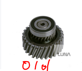
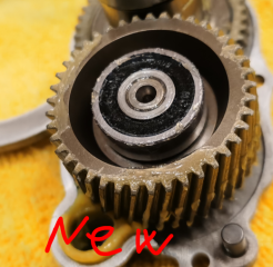
Last edited:
TPEHAK
🚴♂️ Mega poster
Chopped off the XT60 connector from the Kunlun battery leads and soldered XT90-S spark arresting connector with XT90-S to XT60 cable.


TPEHAK
🚴♂️ Mega poster
The moment of truth is getting closer guys!

morinbrett69.
🧲 New user
TPEHAK
🚴♂️ Mega poster
It is almost ready guys! Installed heavy duty steel chainring and heavy duty drivetrain to handle the power.

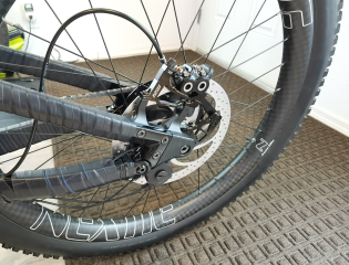

Last edited:
TPEHAK
🚴♂️ Mega poster
We did it guys! It works including the torque sensor and everting else! The walk mode works properly too (it looks like the motor needs some initial resistance and to spin the motor at low speed at walk mode, so on the bicycle it works just fine).
By the way the new Bafang speed sensor needs to be places far from moving metal objects if you don't want to use it as signal source. It picked the brake rotor spokes as signal and the speed reading was too fast so I just zip tied it on the chain stay and put a regular magnet on the rear wheel spoke and it works properly that way. I could leave the sensor at the rear brake rotor but that probably requires changing the firmware to set the proper ratio between the speed sensor signal and the the speed and the VESC application allows only to select the wheel size which is limited only by 26", 27.5" and 29" wheels and you can not trick the program selecting smaller wheel size.
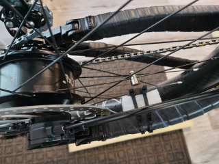
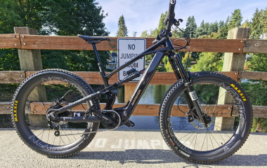
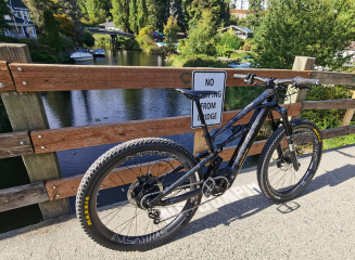
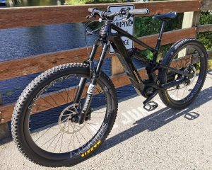

This is basically it guys, the reverse engineering is complete and the controller is tested and it works! I will upload the updated controller cover CAD model which now fits both Dengfu frames and Markhor Kunlun frame.
Now I just need to build new battery to have moar power!
By the way the new Bafang speed sensor needs to be places far from moving metal objects if you don't want to use it as signal source. It picked the brake rotor spokes as signal and the speed reading was too fast so I just zip tied it on the chain stay and put a regular magnet on the rear wheel spoke and it works properly that way. I could leave the sensor at the rear brake rotor but that probably requires changing the firmware to set the proper ratio between the speed sensor signal and the the speed and the VESC application allows only to select the wheel size which is limited only by 26", 27.5" and 29" wheels and you can not trick the program selecting smaller wheel size.
This is basically it guys, the reverse engineering is complete and the controller is tested and it works! I will upload the updated controller cover CAD model which now fits both Dengfu frames and Markhor Kunlun frame.
Now I just need to build new battery to have moar power!
TPEHAK
🚴♂️ Mega poster
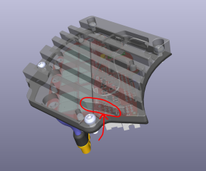
Alrighty guys, here is the final release files. No PCB changes, just updated the controller cover to fit Markhor Kunlun frame also in addition to Dengfu frames.


I never used M600 with stock controller so I do not know. I spun M600 with VESC and M560RS with its stock controller on a bench and M560RS sounds quieter.
I think controller makes no difference in sound level. But it looks like Bafang changed the rotor gear and second gear with finer tooth peach (same they did with Bafang M620) which is probably why M560RS sounds quieter. I know with M620 this change made huge difference in sound level.
View attachment 378029
View attachment 378030
Hi,
I meant in terms of the whining noise, which is partly caused by the type of signal the original controller uses to drive the motor coils. As I understand it, the original controller sends a square wave signal into the coils, which generally results in worse acoustic performance, whereas the VESC controller sends a sine wave — leading to a smoother and quieter sound.
TPEHAK
🚴♂️ Mega poster
I think the gears meshing sound prevails over other motor noises. The M560RS with Bafang controller sounded quieter than M600 with Luna controller on the bench. Maybe there is a difference in sound level between the controllers on the same motor, but I do not have stock Bafang M600 controller or VESC M560 controller to test it and I do not have experience with it.
But I do have experience with stock Bafang M620 UART controller and VESC for m620 UART controller and I think they sound the same on the same motor (or at least they sound close enough to not get my attention).
But I do have experience with stock Bafang M620 UART controller and VESC for m620 UART controller and I think they sound the same on the same motor (or at least they sound close enough to not get my attention).
Last edited:

stancecoke
🏍️ Giga poster
There seem to be a kind of "new generation" Bafang controllers, that are using FOC, just like the VESC.The M560RS with Bafang controller sounded quieter
I can only say my M600 had a 'decent' amount of whine on the stock Bafang controller. Not obnoxious by any means and above 15-20mph, the wind in my ears totally drowned it out, anyway.
Unfortunately, when I switched to a Luna V2 controller, I took the time to tear the motor down, clean it and install some quality grease. The motor was desperately in need of lube after only a few hundred miles on the factory installed grease - the pinion gears were already showing signs of pretty heavy galling.
When I got everything reinstalled, it seemed to be quieter on the Luna V2, but I don't know how much of that was due to the added grease.

Unfortunately, when I switched to a Luna V2 controller, I took the time to tear the motor down, clean it and install some quality grease. The motor was desperately in need of lube after only a few hundred miles on the factory installed grease - the pinion gears were already showing signs of pretty heavy galling.
When I got everything reinstalled, it seemed to be quieter on the Luna V2, but I don't know how much of that was due to the added grease.
Attachments

While it is true, VESC is just superior when it comes to configurability and features. Bafang firmware will be closed for the end user for sure, or require expensive hardware to flash and change parameters.There seem to be a kind of "new generation" Bafang controllers, that are using FOC, just like the VESC.
stancecoke
🏍️ Giga poster
No, if we manage to understand how the Bafang bootloader works, we can flash an open source firmware via CAN. The needed USB to CAN module costs less than $10 and the PC tool to set the parameters or flash an individual bin file already exists as an open source project.expensive hardware
Last edited:
TPEHAK
🚴♂️ Mega poster
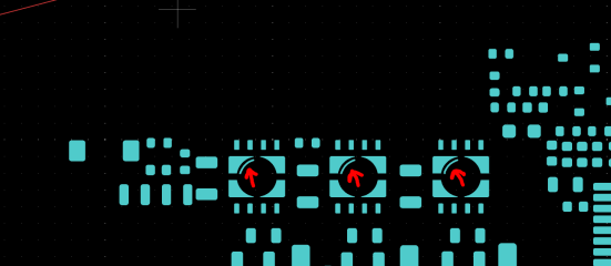
Found a little artifact on the solder paste layer on the MOSFET gate driver footprint. It does not affect anything and the stencil maker will likely remove it anyway because of it is in the hole area but I fixed it anyway and updated the KiCAD files and the Gerber files.
TPEHAK
🚴♂️ Mega poster
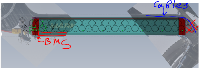
Started mocking up the custom battery for the controller and it looks like 16S3P is the best we can do with this frame. So it is going to be 60V 50A 3000W which is probably good because of this is a standard Luna controller tune.

TPEHAK
🚴♂️ Mega poster
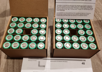
Today is gonna be epic! The juicy battery cells have arrived!
ivannnivano2000
🔌 New-ish
Hello !Correct me if I'm wrong! 3P is only 15A, not 50A. And your battery will be 900 watts!Started mocking up the custom battery for the controller and it looks like 16S3P is the best we can do with this frame. So it is going to be 60V 50A 3000W which is probably good because of this is a standard Luna controller tune.
View attachment 380155
View attachment 380156
TPEHAK
🚴♂️ Mega poster
These are Samsung 50S cells. Each cell is capable 25A continuous. Therefore 3P is going to be 25A × 3 = 75A. The BMS I am going to use limits the current to 60A. The Luna firmware predefined maximum setting is 50A (but I can set any on the controller up to what the BMS is capable of). So the current is going to be limited by the motor controller, it is 50A. 50A × 60V = 3000W.
But the battery cells can safely give even more, 75A in 3P configuration, it just needs appropriate BMS for such current and the settings on the motor controller.
But the battery cells can safely give even more, 75A in 3P configuration, it just needs appropriate BMS for such current and the settings on the motor controller.
TPEHAK
🚴♂️ Mega poster
Designed and 3D printed a cover for the charging connector and BMS ON/OFF button for the Kunlun frame for the new battery.
It looks like the Kunlun bicycle uses proprietary charging connector so I ended up placing a common 5.5x2.1mm dc plug most chargers use on the cover
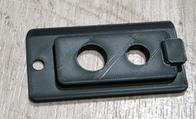


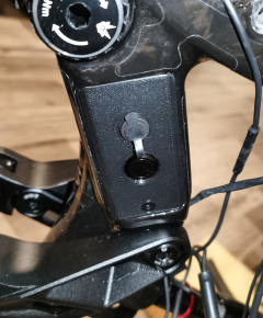
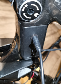
The original cover vs 3D printed

It looks like the Kunlun bicycle uses proprietary charging connector so I ended up placing a common 5.5x2.1mm dc plug most chargers use on the cover
The original cover vs 3D printed
TPEHAK
🚴♂️ Mega poster
The BMS from Green Bike Kit has arrived!

Last edited:

These are Samsung 50S cells. Each cell is capable 25A continuous. Therefore 3P is going to be 25A × 3 = 75A. The BMS I am going to use limits the current to 60A. The Luna firmware predefined maximum setting is 50A (but I can set any on the controller up to what the BMS is capable of). So the current is going to be limited by the motor controller, it is 50A. 50A × 60V = 3000W.
But the battery cells can safely give even more, 75A in 3P configuration, it just needs appropriate BMS for such current and the settings on the motor controller.
Please keep in mind that the maximum rated continuous current is based on lab tests at a fixed temperature in ambient air.
The limit is determined by the point where the cell barely doesn't explode from thermal runaway.
When you put a bunch of cells together, inside a case, that's a totally different thermal environment and you either need temperature monitoring to cutoff power when it gets too hot, or to derate the heck out of them when in a pack configuration.
Before you hit thermal limits, you get a ton of sag. If you run 20A on this cell, you will get something that looks like lifepo4 nominal voltages, which will dampen your thrill. Here is a discharge graph on that cell at various amperages
( notice that at 30A, the test was cut off early due to heat.. )

Also mind that this large amount of sag also hurts your capacity since >20% of the cell's energy is being turned into heat instead of power once we're near the thermal maximum.
Also once you get down to freezing temperatures, whatever the cell voltage drop is at 'room temperature', it should be 3x-4 that at the freezing point, until the pack heats itself up ( if it can ). If you are in Idaho and ride in the cold, this is a factor to consider.
I'd consider adding another one of those cells in parallel if you are thinking of doing 60A and it's not too late to make the change.
50S is not a very powerful cell, it just happens to accept higher temperatures before exploding and sag more to produce this lofty 25A output ( and only in hyper-ideal conditions ) figure

Nix Liou
⚡ Regular
Seconding- The 50S is honestly pretty mid. Consider the eve 40pl or 50pl, reliance rs50, tenpower 50xg, or various molicel options (especially for low temps) like the p50b, or p45b. All of these would outperform the 50S for CDR and cycle life (the fatal flaw of the 50S)
TPEHAK
🚴♂️ Mega poster
The battery cage CAD model is mostly complete. Did some test prints out of glass filled nylon to check the fitment. So far so good!


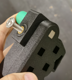


Last edited:
TPEHAK
🚴♂️ Mega poster
For someone who might still wondering about some mysterious circuits on the PCB. I started digging into the VESC firmware and it looks like one of those circuits is connected to the "LED_RED" function pin PB11 on the MCU while the actual red LED on the PCB is connected to auxiliary pin PC14


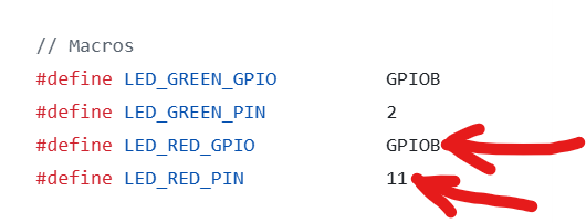
It looks like he used that circuits just for the development stage to connect an LED light externally and observe outside the motor externally if 5V is presented (dimmed LED light) and faults events (bright LED light) so it looks like that weird circuit is just a development artifact.

It looks like he used that circuits just for the development stage to connect an LED light externally and observe outside the motor externally if 5V is presented (dimmed LED light) and faults events (bright LED light) so it looks like that weird circuit is just a development artifact.
Last edited:
Similar threads

- Replies
- 86
- Views
- 9,359
- Replies
- 77
- Views
- 5,386

- Replies
- 103
- Views
- 16,425
- Replies
- 35
- Views
- 7,803