My new 18 FET TO-247 layout riding video page 10

Setting the Amplitude control to 1200 and 60 seemed to make the current waveform more sinusoidal at low speed. The motor's inductance is about 12uH phase to phase; perhaps this is why we needed to set that parameter so high?
 
toolbag said:
Setting the Amplitude control to 1200 and 60 seemed to make the current waveform more sinusoidal at low speed. The motor's inductance is about 12uH phase to phase; perhaps this is why we needed to set that parameter so high?

Hm, the 1200 is the proportional part in the control loop, it is there for stability. The 60 is the one that matters I think (the actual increase or decrease of the signal amplitude, supply voltage * 60/65536), the relatively high value means the control loop will respond with relatively big steps meaning it can correct quickly. The 1200 adds a lot of noise though (supply voltage * 1200/65536) , I would try to reduce that one.
More interestingly though is that with lower values it's the saturation detection that trips, not the controller IC. I wonder what advantage it could be to the saturation detection that the outputted voltages have quite some noise.... As mentioned before, with the 1200 when the motor is up to speed, it will clip a lot more enthousiastically than with a lower value. So maybe it is not the added noise but the (earlier) clipping allows proper reset of the saturation detection ?
 
Here is the video we took while testing the controller out. I tried to capture a little bit of everything, faults, tuning issues, success and awesomeness.

[youtube]E_la_VfrjTM[/youtube]
 
Cool stuff :shock:

I had a look at the hex, apparently the current sensors are only 3.12 mV/A, are they 600 A sensors ?

Anyways, event at 150 A amplitude you're talking only 500mV (1Vpp) into the controller IC. Your error current settings
are 25A and 25A, so 80 to 160 mV. All these are quite low values keeping in mind the ADC's in the chip have about
5mV per LSB. Noise picked up between the current sensors and the controller IC will can have quite an impact with
these small signal amplitudes

If you want to use these sensors, have you considered looping the phase wires 3 or 4 times through the sensor ? This
would turn the 600A sensors into 200A or 150A sensors, and make 'm 9.36 mV/A or 12.48mV/A as far as the controller
IC is concerned. The effect of picked up noise would be reduced by a factor 3 to 4.

When you go to maximum 200A phase current, wouldn't ACS758 type sensors be a better choice ?

Did you have a look at the sine wave frequency on toolbags labview setup ? What was the real-life erpms reached ?
 
Lebowski said:
Zombiess, in the video your output stage once trips the the desat... have you checked whether this is maybe due to the reverse recovery taking too long ?

Output stage desat trips when the controller loses sync and faults to DRIVE 0. I've had many instances of it tripping when tuning parameters are wrong. Once the parameters are closer to running there are less desat faults, but still some DRIVE 0 faults, however once faulted it's possible to restart most of the time.

If it were a long RR time due to the body diode, the controller would be experiencing lots of desat trips at high current where there is more energy, but that is not the case. In fact the opposite is true. We experienced less desat faults at 12kW than we did at 1kW. Of course once we had the parameters that ran we stopped getting desat faults at any power level. I could make the controller fault with fast throttle transitions, but no desat fault triggered.

As for the 600A current sensors, that was planned as I am testing for future designs and trying to learn what works and what doesn't. Those 600A sensors worked well, my 1800A sensors, not so much. I'm surprised they work as well as they do given the noise levels which can be found. I believe running everything from isolated supplies greatly aids performance.

One issue I keep running into is it's often difficult to get the controller to go from DRIVE 0 to DRIVE 2. I have to have the stand still voltage set to 1.98V which is as high as it goes and even then I sometimes need to physically touch or ground the brain board to get it to switch to DRIVE 2. Thoughts on this issue?
 
zombiess said:
One issue I keep running into is it's often difficult to get the controller to go from DRIVE 0 to DRIVE 2. I have to have the stand still voltage set to 1.98V which is as high as it goes and even then I sometimes need to physically touch or ground the brain board to get it to switch to DRIVE 2. Thoughts on this issue?

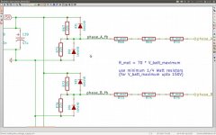
This means somehow current is leaking via the output stage and the voltage measurement resistors into the 5V circuitry.
schematic.jpg
Your circuitry is maybe a bit different but the functionality is the same. When looking at phase_A, on the right is the motor terminal which is of course also connected to the output stage. The voltage on phase_A_fb is what the controller Ic looks at. When both high and low side of the output stage are off, phase_A is in effect connected to nothing (OK, via the motor to phase_B and phase_C, but not to the battery or ground). The voltage on phase_A_fb is 2.5 V, the 5V divided in half by R67 and R71. There is no current coming through the R_mot resistors.

In normal functioning, when the motor makes back-emf this this appears (divided down) on phase_A_fb. The controller IC sees this and knows the motor is turning. The setting in the menu is how much the voltage is allowed to deviate from the 2.5V midpoint, before the controller Ic declares the motor running or not.

In your case, some current is leaking into or out of the phase_A connection, flowing through R_mot and affecting the voltage on phase_A_fb.... if you put your multimeter on this point you'll see it is not 2.5V ...
 
Back
Top