latecurtis
100 MW
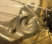
Nothing is simple with this. Had to file for an hour to make that work . I still got to file the other washer and the lawers lip on the other side. Please tell me if the wheel is on the right side of the bike. Hope to get this thing going tommorow. Also is it ok to charge the batteries tonight when I get back from posting this. Will be at the library tommorow for some final answers. Thanks Latecurtis.