
You are using an out of date browser. It may not display this or other websites correctly.
You should upgrade or use an alternative browser.
You should upgrade or use an alternative browser.
New "TSDZ2 Torque Sensor Central Motor"
- Thread starter larsottar
- Start date
casainho
10 GW
- Joined
- Feb 14, 2011
- Messages
- 6,058
See here a possible solution: https://github.com/OpenSource-EBike-firmware/TSDZ2_wiki/wiki/How-to-install-TSDZ2-on-a-full-suspension-bicycleDaught said:My motor casing is starting to develop some cracks. I can't install the big rear bracket because of the suspension I have on my bike. If it breaks, are there any sources for the aluminum case?
I went back and I say your pics of the other cracked motor. I wonder what exactly causes the motor to crack.
1. In my case, the front non-drive side bottom bracket attachment ears hit the frame. I believe as the motor twists in the bottom bracket it causes the ear to push the motor out and ends up cracking the case. Did your ear also hit the frame ? I could build a bracket that prevents the motor from twisting.
2. The motor just exerts a lot of torque. It needs the rear attachment bracket to support it and distribute the force
The main question if the rear bracket only there only prevent the motor from twisting, or it is a critical support component? Considering how beefy it is, I am inclined to believe it provides support.
Hi. See my photos on page 114. I repair the body and drive after this almost 1000 kmDaught said:I went back and I say your pics of the other cracked motor. I wonder what exactly causes the motor to crack.
1. In my case, the front non-drive side bottom bracket attachment ears hit the frame. I believe as the motor twists in the bottom bracket it causes the ear to push the motor out and ends up cracking the case. Did your ear also hit the frame ? I could build a bracket that prevents the motor from twisting.
2. The motor just exerts a lot of torque. It needs the rear attachment bracket to support it and distribute the force
The main question if the rear bracket only there only prevent the motor from twisting, or it is a critical support component? Considering how beefy it is, I am inclined to believe it provides support.
casainho
10 GW
- Joined
- Feb 14, 2011
- Messages
- 6,058
Here is the final design (I hope):
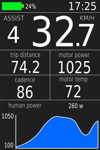
- break and lights symbol (not show on the image) should appear at top, in the middle
- the four fields at the middle can be customized: the data to be shown at each filed can be one of the many variables available, like the ones that are shown on KT-LCD3 odometer field
- the graph field can be customized: the data to be shown can be one of the many variables available, like the ones that are shown on KT-LCD3 odometer field, user will need to define the graph time to be 10, 20 or 30 minutes.
mctubster said:casainho said:Thanks!! that was the help I though I would need. I will look at that source files and try to play with them as I like your design, HOWEVER, I plan to use like 1/3 the screen, at bottom, for a graph where a variable is shown -- this is something I want much and I think would be really great to have a graph showing like last 30 minutes (LCD 300 pixels width, 300/30 --> 6 seconds each pixel).
The graph must have a label showing the variable name as also scale, and maybe the scale of Y will be automatic while X scale can at start to be like the last 30 minutes.
Sounds great. No idea how hard this is to implement - The large Garmin cycle computers have an interesting setup where you setup multiple "screens" and customise what is displayed in each field
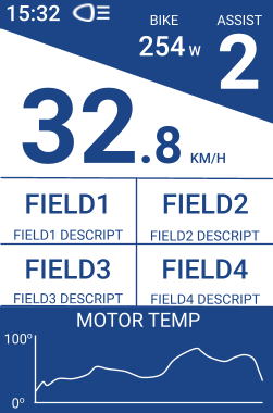
In the configuration you choose for screen 1
FIELD1 = TRIP DISTANCE,
FIELD2 = TRIP TIME
FIELD3 = CADENCE
FIELD4 = ODO
GRAPH = MOTOR TEMPERATURE
Then you configure screen 2 (which you switch to/from using a short press on the power button for example)
FIELD1 = TRIP DISTANCE
FIELD2 = HUMAN POWER
FIELD3 = CADENCE
FIELD4 = MOTOR TEMP
GRAPH = BATTERY CURRENT
This way you let people configure what they want to see on their main screen as well as easy to switch to other combinations.
Nice work. How did yours break?Kisazul said:Hi. See my photos on page 114. I repair the body and drive after this almost 1000 kmDaught said:I went back and I say your pics of the other cracked motor. I wonder what exactly causes the motor to crack.
1. In my case, the front non-drive side bottom bracket attachment ears hit the frame. I believe as the motor twists in the bottom bracket it causes the ear to push the motor out and ends up cracking the case. Did your ear also hit the frame ? I could build a bracket that prevents the motor from twisting.
2. The motor just exerts a lot of torque. It needs the rear attachment bracket to support it and distribute the force
The main question if the rear bracket only there only prevent the motor from twisting, or it is a critical support component? Considering how beefy it is, I am inclined to believe it provides support.
Daught said:Nice work. How did yours break?
See pages 114, 113, 112 and maybe even earlier
linklemming
10 mW
- Joined
- Aug 25, 2011
- Messages
- 34
casainho said:Here is the final design (I hope):
- break and lights symbol (not show on the image) should appear at top, in the middle
- the four fields at the middle can be customized: the data to be shown at each filed can be one of the many variables available, like the ones that are shown on KT-LCD3 odometer field
- the graph field can be customized: the data to be shown can be one of the many variables available, like the ones that are shown on KT-LCD3 odometer field, user will need to define the graph time to be 10, 20 or 30 minutes.
mctubster said:casainho said:Thanks!! that was the help I though I would need. I will look at that source files and try to play with them as I like your design, HOWEVER, I plan to use like 1/3 the screen, at bottom, for a graph where a variable is shown -- this is something I want much and I think would be really great to have a graph showing like last 30 minutes (LCD 300 pixels width, 300/30 --> 6 seconds each pixel).
The graph must have a label showing the variable name as also scale, and maybe the scale of Y will be automatic while X scale can at start to be like the last 30 minutes.
Sounds great. No idea how hard this is to implement - The large Garmin cycle computers have an interesting setup where you setup multiple "screens" and customise what is displayed in each field
In the configuration you choose for screen 1
FIELD1 = TRIP DISTANCE,
FIELD2 = TRIP TIME
FIELD3 = CADENCE
FIELD4 = ODO
GRAPH = MOTOR TEMPERATURE
Then you configure screen 2 (which you switch to/from using a short press on the power button for example)
FIELD1 = TRIP DISTANCE
FIELD2 = HUMAN POWER
FIELD3 = CADENCE
FIELD4 = MOTOR TEMP
GRAPH = BATTERY CURRENT
This way you let people configure what they want to see on their main screen as well as easy to switch to other combinations.
casainho,
That display and functionality would be AWESOME, I spent today going thru marcoqs changes for the VCLD6 to confirm what was being done but in the end its going to cost about $100US to convert. I also worked on getting everything to fit on my handlebars with the LCD3 in case I wanted to go back to that but this change would suit me better.
Hi all. I just flashed KT-LCD3 on the way to trying the open source firmware.
Thanks jbalat & andyme for instructions and of course casainho for all the effort.
A couple questions:
1. The ST V link I have puts out 3.3V, not 5V. It seemed to work but the LCD was super dim. Is it OK to use 5V from another source?
2. Before I flash the motor, where are the torque sensor calibration constants stored? In the motor or the VLCD5? How do I prevent losing them and get them into the new setup?
Thanks
Connectorized KT-LCD3.
Flashing the KT-LCD3 requires opening the case and making connections to the J7 holes on the PCB. Various ideas are on the forum, here is another.
I used a 4-pin JST-XH connector, which can be soldered directly to PCB holes and fits nicely after a clearance hole is cut in the back of the KT-LCD3 case.

Here is the connectorized KT-LCD3 before I sealed the connector with hot glue.
JST-XH is the connector used for balance connection on RC batteries, so they are cheap and available. In standard use you need a special pin crimper for the mating side (not the side that solders to the PCB), but for a test cable I think you can get by without the crimper.
Flashing the KT-LCD3 requires opening the case and making connections to the J7 holes on the PCB. Various ideas are on the forum, here is another.
I used a 4-pin JST-XH connector, which can be soldered directly to PCB holes and fits nicely after a clearance hole is cut in the back of the KT-LCD3 case.
Here is the connectorized KT-LCD3 before I sealed the connector with hot glue.
JST-XH is the connector used for balance connection on RC batteries, so they are cheap and available. In standard use you need a special pin crimper for the mating side (not the side that solders to the PCB), but for a test cable I think you can get by without the crimper.
casainho
10 GW
- Joined
- Feb 14, 2011
- Messages
- 6,058
Very good idea/connector, I must say!! I have that connectors on stock and didn't had the idea to use them, like that, much better then what I did.tomtom50 said:Connectorized KT-LCD3.
Flashing the KT-LCD3 requires opening the case and making connections to the J7 holes on the PCB. Various ideas are on the forum, here is another.
I used a 4-pin JST-XH connector, which can be soldered directly to PCB holes and fits nicely after a clearance hole is cut in the back of the KT-LCD3 case.
JST-XH soldered onto PCB.jpg
Here is the connectorized KT-LCD3 before I sealed the connector with hot glue.
Connectorized KT-LCD3 before sealing with hot glue.jpg
JST-XH is the connector used for balance connection on RC batteries, so they are cheap and available. In standard use you need a special pin crimper for the mating side (not the side that solders to the PCB), but for a test cable I think you can get by without the crimper.
casainho said:Here is the final design (I hope):
Looks fantastic. Appreciate your hard work on this. Best place to buy a new display from for international shipping? (Australia)
Waynemarlow
10 kW
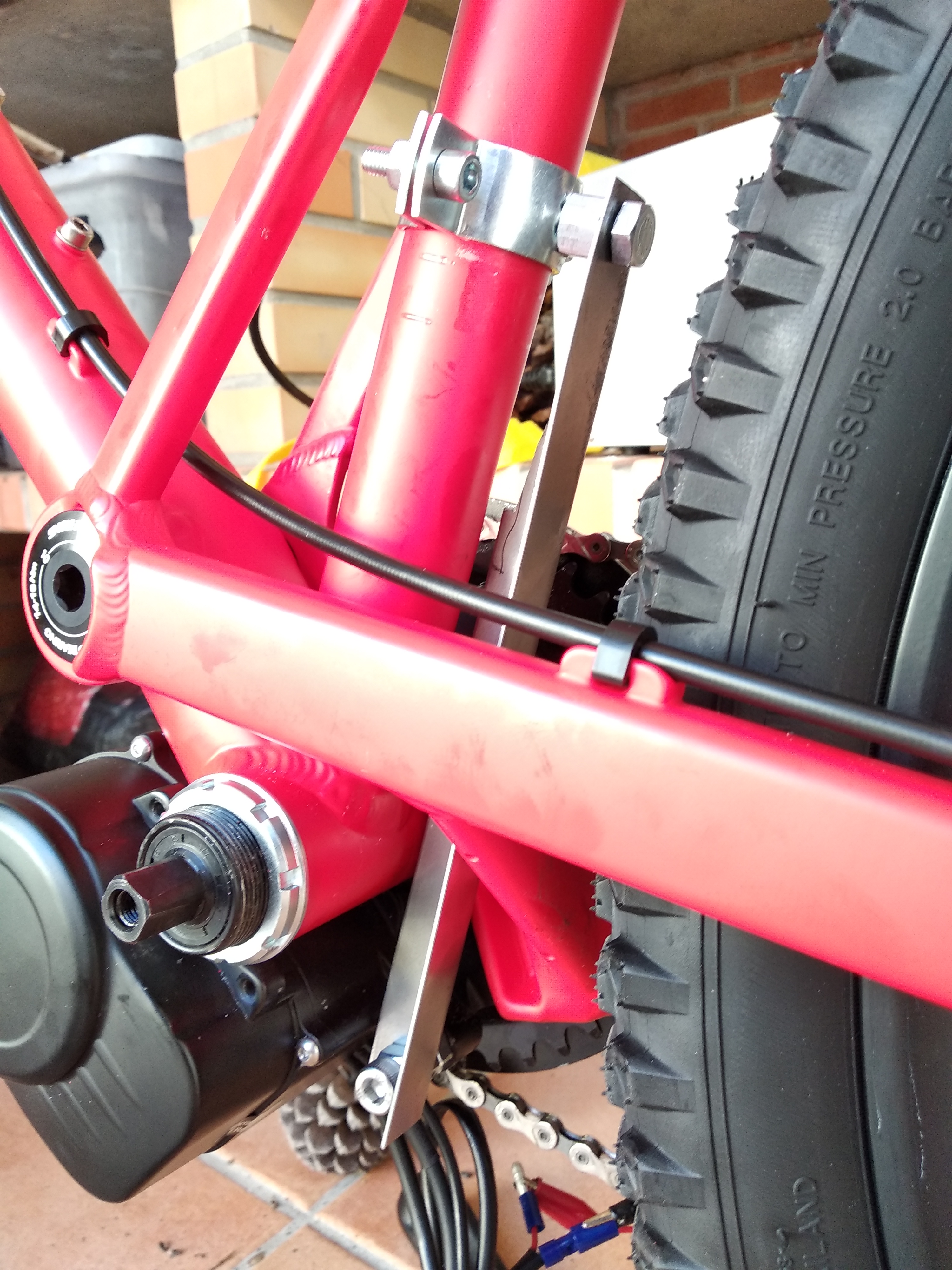
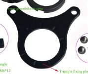
Daught said:Rod going through the swingarm without interference through the whole stroke. I might have to double up the brackets to prevent flex.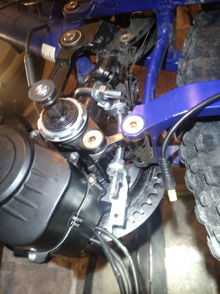
Guys this is so over the top engineering, that would support the torque of V8 engine let alone the torque of a small electric engine.
Can I ask a question as to why you are not using the very important left hand side outer bracket that bolts onto the bottom bracket ( or perhaps you are and you just haven't fitted it in this photograph ) ? This outer small bracket that is supplied with the kit is fundamental to the way the engine grips the BB and aides in stopping any tendency to rotate. It also stops any 45 degree twisting motion of the engine under torque which does two things, breaks the inner casing which a few people are reporting and it also stops the engine torque being not purely rotational, but as in the photograph above with a 45 degree bias. That bias is what is causing the large outer nut to loosen and then the unit rotating.
That little outer bracket is not difficult to fit and I can't really understand why people are not using it. Yes you will have to use a small amount of engineering nous to " shim " it using small Stainless Steel washers to compensate for the depth of your bottom bracket or any variances.
We've now done nearly 1200 miles on two late full suspension bikes without any need for a torque limiting bracket on particularly hilly off road terrain, both are still in the exact position we put them in when we torqued up that big outer nut, I'm really not sure why others are having problems. I do admit to altering my outer bracket slightly though and followed the Bafang route of putting a few extra notches in the surface of the bracket ( I was running about 1600W through a BBS series engine without the need of a torque arm ) using a few centre punch points.
Attachments
Waynemarlow said:Daught said:Rod going through the swingarm without interference through the whole stroke. I might have to double up the brackets to prevent flex.
Guys this is so over the top engineering, that would support the torque of V8 engine let alone the torque of a small electric engine.
Can I ask a question as to why you are not using the very important left hand side outer bracket that bolts onto the bottom bracket ( or perhaps you are and you just haven't fitted it in this photograph ) ?
Waynemarlow, your concern is absolutely correct. I corresponded with Casainho about this and he actually did put the bb bracket on his actual install. The image he posted is just to show the anti-rotation bracket he fabricated. I hope others don't see this image and think they can leave the BB bracket off of their install. As for Daught, he is likely going to end up splitting open the case on the gear reduction side as has happened to others that left off the BB bracket.
casainho said:Here is the final design (I hope):
- break and lights symbol (not show on the image) should appear at top, in the middle
- the four fields at the middle can be customized: the data to be shown at each filed can be one of the many variables available, like the ones that are shown on KT-LCD3 odometer field
- the graph field can be customized: the data to be shown can be one of the many variables available, like the ones that are shown on KT-LCD3 odometer field, user will need to define the graph time to be 10, 20 or 30 minutes.
Looks great. Can't wait. Actual voltage number would be very useful as an option or instead of % since the graphic also communicates %.
Hi, Just to confirm does this firmware have the ability to change from street legal (e.g. 25kph and 250w settings ) to custom settings (unrestricted kph and 750w - depending on motor wattage) and back quickly through the pressing of a button/button combination? In the event that one was stopped by police so they could only see the street legal settings on the display?
linklemming
10 mW
- Joined
- Aug 25, 2011
- Messages
- 34
Minatauro said:Hi, Just to confirm does this firmware have the ability to change from street legal (e.g. 25kph and 250w settings ) to custom settings (unrestricted kph and 750w - depending on motor wattage) and back quickly through the pressing of a button/button combination? In the event that one was stopped by police so they could only see the street legal settings on the display?
The opensource firmware has this ability using 'offroad mode'.
I have mine setup with this, simple (+ and power button) press turns it on and (- and power button) turns it off. You can also set which mode you want on powerup.
linklemming said:Minatauro said:Hi, Just to confirm does this firmware have the ability to change from street legal (e.g. 25kph and 250w settings ) to custom settings (unrestricted kph and 750w - depending on motor wattage) and back quickly through the pressing of a button/button combination? In the event that one was stopped by police so they could only see the street legal settings on the display?
The opensource firmware has this ability using 'offroad mode'.
I have mine setup with this, simple (+ and power button) press turns it on and (- and power button) turns it off. You can also set which mode you want on powerup.
Excellent, thank you for that, I cant wait for my motor to arrive so I can convert my bike.
Ron Paul's Blimp
10 W
- Joined
- Jun 12, 2017
- Messages
- 87
I finished the main parts of my build and just took it out for the first real test ride. I have a 'new'-type (black chainring adapter) 48V from pswpower with a 52V battery and the stock firmware (I want to get a solid feel for what the stock firmware is like before beginning to mess with the opensource).
My first impression is holy hell it's even louder than I feared it would be after reading this thread. Even in assist level 1, even lightly pedaling, it sounds like an RC car. Really disappointing and it might be a bit of a deal-breaker if the opensource firmware doesn't help somehow. Unfortunately I don't know what else I'd use since I don't know of any other torque-sensing mid-drives in its weight class that don't require a custom frame. Huge bummer.
My second impression is that it feels a little hamstrung on the steepest hills (15% - 20% grade). I think the problem might be that maybe it's locked into the default 250W mode. I wasn't able to get to the menu to view / change that (I have a VLCD6, so supposedly it's done by holding down all three buttons, but I can't for the life of me .. I must have tried 50 times).
With the stock firmware, an unscrupulous rider might put the display into km/h, and scale the wheel diameter setting down by the ratio of km to miles. Then the display will say, for example, 35 km/h (22 mph), when you're actually doing 35 mph. I can't get my display to show me the power limit, so if a cop's able to do that somehow, more power to them.
My first impression is holy hell it's even louder than I feared it would be after reading this thread. Even in assist level 1, even lightly pedaling, it sounds like an RC car. Really disappointing and it might be a bit of a deal-breaker if the opensource firmware doesn't help somehow. Unfortunately I don't know what else I'd use since I don't know of any other torque-sensing mid-drives in its weight class that don't require a custom frame. Huge bummer.
My second impression is that it feels a little hamstrung on the steepest hills (15% - 20% grade). I think the problem might be that maybe it's locked into the default 250W mode. I wasn't able to get to the menu to view / change that (I have a VLCD6, so supposedly it's done by holding down all three buttons, but I can't for the life of me .. I must have tried 50 times).
Minatauro said:Hi, Just to confirm does this firmware have the ability to change from street legal (e.g. 25kph and 250w settings ) to custom settings (unrestricted kph and 750w - depending on motor wattage) and back quickly through the pressing of a button/button combination? In the event that one was stopped by police so they could only see the street legal settings on the display?
With the stock firmware, an unscrupulous rider might put the display into km/h, and scale the wheel diameter setting down by the ratio of km to miles. Then the display will say, for example, 35 km/h (22 mph), when you're actually doing 35 mph. I can't get my display to show me the power limit, so if a cop's able to do that somehow, more power to them.
Ron Paul's Blimp said:My first impression is holy hell it's even louder than I feared it would be after reading this thread. ...
My second impression is that it feels a little hamstrung on the steepest hills (15% - 20% grade).
I think the problem might be that maybe it's locked into the default 250W mode. I wasn't able to get to the menu to view / change that (I have a VLCD6, so supposedly it's done by holding down all three buttons, but I can't for the life of me .. I must have tried 50 times).
Some motors are louder than others. The open source firmware in my experience is nominally quieter and more efficient.
The open source firmware unlocks all the power the motor has. You can burn it up if you are not careful and have not added the temp sensor.
The stock firmware is locked into a maximum wattage and none of the stock displays can change it. You can reprogram it to different max watt levels but that is as hard as doing the opensource and the opensource firmware is much better. There is work being done on the open source thread by Marcoq to allow you to use the VLCD6 display with the opensource firmware.
Ron Paul's Blimp
10 W
- Joined
- Jun 12, 2017
- Messages
- 87
Rydon said:Some motors are louder than others. The open source firmware in my experience is nominally quieter and more efficient.
I wish I knew what the variable was so I could try to make mine quieter. I'm going to need a lot more than a nominal improvement to get it down to what I'd like (I'm used to a BBS02, which is insanely quieter than this).
The stock firmware is locked into a maximum wattage and none of the stock displays can change it. You can reprogram it to different max watt levels but that is as hard as doing the opensource and the opensource firmware is much better. There is work being done on the open source thread by Marcoq to allow you to use the VLCD6 display with the opensource firmware.
Supposedly the VLCD6 can change the max power, but I haven't been able to get the buttons pressed in the right way. I have an LCD3 and flashed it already and made the connector to flash the controller, I just wanted to get a few miles in with everything stock first to have a baseline for comparison. Yeah, I'm the guy in the other thread who's planning to try to bring marcoq's vlcd6 work into casainho's tree.
Similar threads
- Replies
- 1
- Views
- 718
- Replies
- 5
- Views
- 2,427

- Replies
- 14
- Views
- 29,117
- Replies
- 1,682
- Views
- 146,803
- Replies
- 23
- Views
- 5,680