mwkeefer
1 MW
+1 subscribed
Postby marcexec » Sun Jan 11, 2015 8:23 pm
Cool, thanks for sharing.
I'll have another go at the 2 USP-500s I broke at some point")
geofft said:Postby marcexec » Sun Jan 11, 2015 8:23 pm
Cool, thanks for sharing.
I'll have another go at the 2 USP-500s I broke at some point
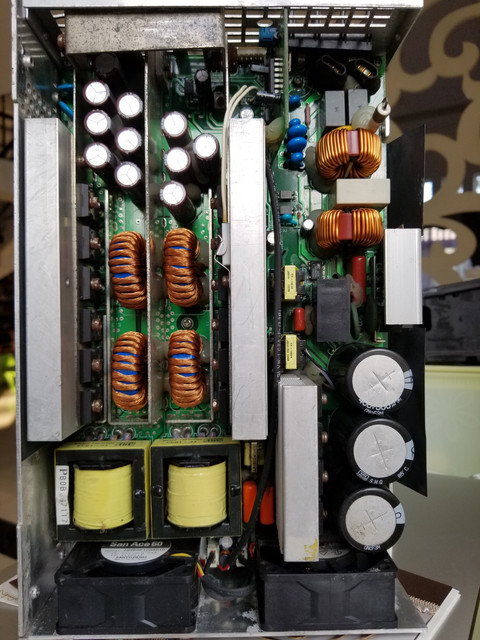
....they look quite different beasts from the S and SP series stuff that many of us seem to delight in exploding.
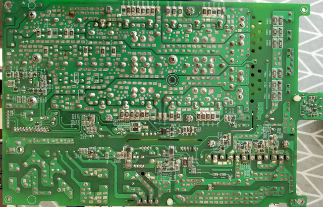
Did you manage to find a circuit diagram for them?
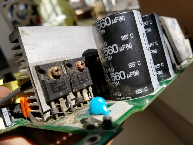
Yeah, it is the right practice and matched if possible. Must say, I did not follow this rule in some cases and got away with. :?pplayer said:Should I replace all 4 power MOSFET if one of them burned?