• Hello ES! We could use some help to get us past the finish line on building the new knowledgebase for the forum.
    Can you donate? Please see our fundraising page. Thank you!

The HI-Lebowski: a Lebowski SMD brain running a zombified Honda IMA Inverter: *a HOW-TO guide*

This may be a really noobish question, but what is the max voltage that this zombie inverter can handle at what current?

I have a 20s scooter for now, but in the future i may reuse it for another 36s scooter while salvaging many of the first elements and components

Edit: after more research than i initially did, i think they are rated at 144v for a total output of around 20kw according to this post : https://www.diyelectriccar.com/threads/honda-ima.163650/post-683089
 
Molten-Core said:
This may be a really noobish question, but what is the max voltage that this zombie inverter can handle at what current?

I have a 20s scooter for now, but in the future i may reuse it for another 36s scooter while salvaging many of the first elements and components

Edit: after more research than i initially did, i think they are rated at 144v for a total output of around 20kw according to this post : https://www.diyelectriccar.com/threads/honda-ima.163650/post-683089

I have run the IMA on 48S lipo ~ 200V hot off the charger. The second gen Civic hybrids use a 158V pack and the IMA inverter used here is from a gen2 hybrid.
 
kiwifiat said:
Molten-Core said:
This may be a really noobish question, but what is the max voltage that this zombie inverter can handle at what current?

I have a 20s scooter for now, but in the future i may reuse it for another 36s scooter while salvaging many of the first elements and components

Edit: after more research than i initially did, i think they are rated at 144v for a total output of around 20kw according to this post : https://www.diyelectriccar.com/threads/honda-ima.163650/post-683089

I have run the IMA on 48S lipo ~ 200V hot off the charger. The second gen Civic hybrids use a 158V pack and the IMA inverter used here is from a gen2 hybrid.


Thanks for sharing that!

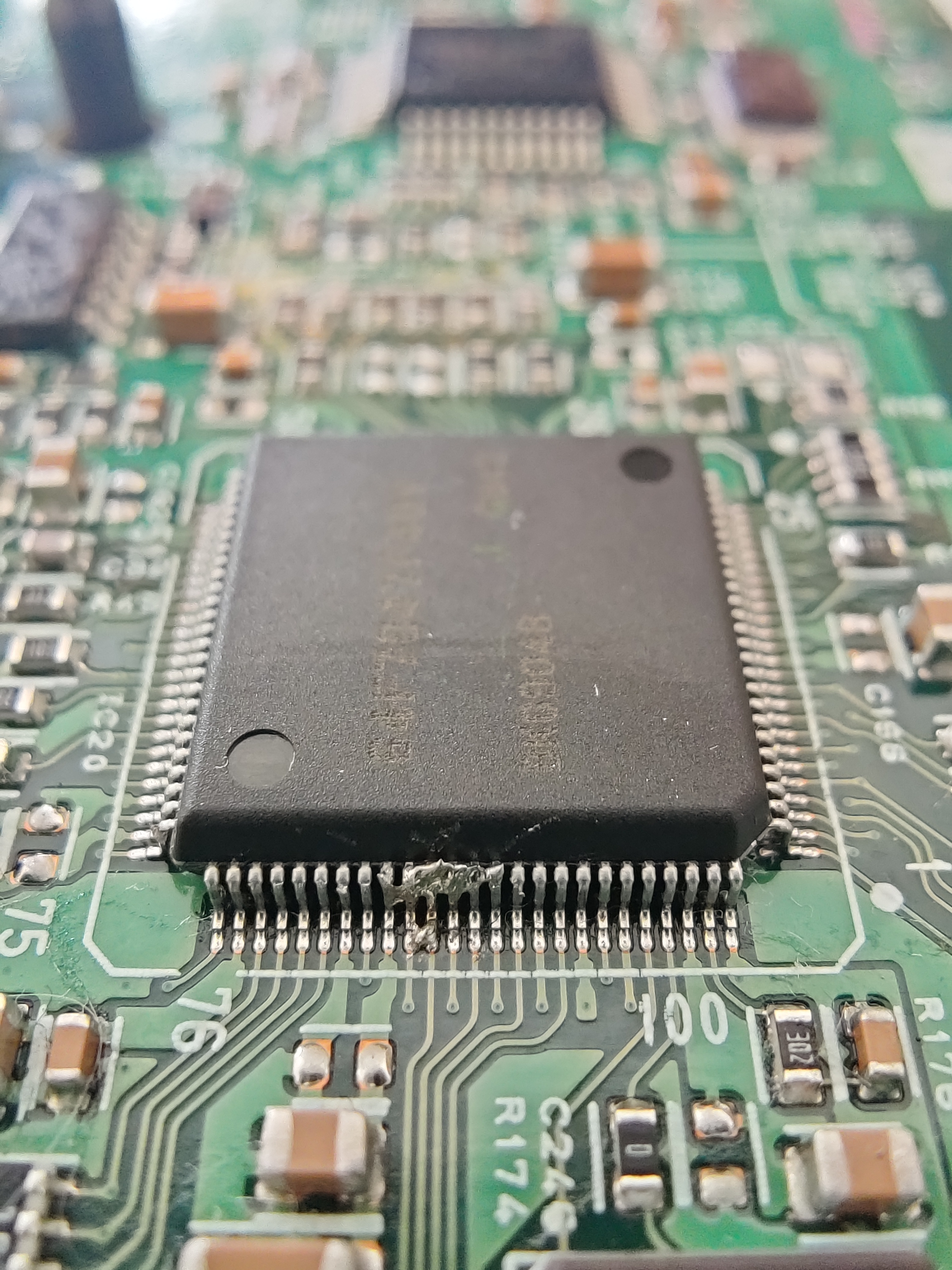
SO, while waiting for my brainboard to arrive i tried to desolder the reset pin and do the mod, but i didnt expect things to turn this sour:
J0llQZc.jpg


Do you guys think if i cut the whole ship out it would still work? I could just dremel out all the pins and clean this traces carrefully, i tried with solder wick and couldn't manage to do anything good

Edit:Is it important to twist the wires?
 
You can easily clean that up. Decent soldering iron, solder braid, flux... It'll come off no problem.
 
mxlemming said:
You can easily clean that up. Decent soldering iron, solder braid, flux... It'll come off no problem.

Just tried again, but my hands are way too shaky, i just broke a pin not far from the reset, isn't it possible to just cut the whole chip out?
 
Molten-Core said:
mxlemming said:
You can easily clean that up. Decent soldering iron, solder braid, flux... It'll come off no problem.

Just tried again, but my hands are way too shaky, i just broke a pin not far from the reset, isn't it possible to just cut the whole chip out?
Hypothetically asserting reset on the chip tristates all the outputs so yes, chopping the chip or should have the same effect.

But who knows :roll: I can say for sure it would work for an stm32 but for that renesas thing...
 
Find something to rest your wrist / hand on. Helps to move your fingers instead of trying to move your whole arm or from your elbow.
Bringing the whole thing up near shoulder height helps too. Don't arch your back, bring the piece up.
Use a thin / sharp tip in the soldering iron and "split" the solder on the pins. You could push the desolder braid in this way too.
 
Molten-Core said:
Just tried again, but my hands are way too shaky, i just broke a pin not far from the reset, isn't it possible to just cut the whole chip out?

Yes you can cut the chip out but you will still need to clean up the pcb pads to ensure there are no shorts.
 

Attachments

  • IMA_CPU_REMOVAL.PNG
    IMA_CPU_REMOVAL.PNG
    188.9 KB · Views: 847
The topic is gone?
How did it end ?
What is the maximum battery and motor current that can be obtained with this inverter? I want to use them with the openinvertor version 3 brain to control the rear engines of the alphard. Capacitors at 600 volts, does this mean that you can try a 400 volt battery?
 
YTW200 said:
The topic is gone?
How did it end ?
What is the maximum battery and motor current that can be obtained with this inverter? I want to use them with the openinvertor version 3 brain to control the rear engines of the alphard. Capacitors at 600 volts, does this mean that you can try a 400 volt battery?

No This inverter will work with max 200Vdc. Any more and EMI will prevent you from having good control.
https://www.diyelectriccar.com/threads/honda-ima.163650/
 
arber333 said:
No This inverter will work with max 200Vdc. Any more and EMI will prevent you from having good control.
https://www.diyelectriccar.com/threads/honda-ima.163650/

Thanks for the reply. And how many amperes can the maximum battery and motor still be?
 
This is just brilliant for a high-voltage "midrange" option!
Also awesome the the Lebowski went open source. I had a through hole board (and 2 chips) but blew up TO247 power stages and went "commercial" when the DCDC blew as well...
I'm going to give this a try - is anyone selling the SMD boards? I'll only mess them up...
 
Quick revive of this, I had a short test with sensorless and the MHM602 at 136V:
See my build/instructions thread as well.
 
See my build/instructions thread as well.
That is here:
in case anyone goes looking for it. :)
 
This might be the solution I need!

I'm using a Hyundai HSG in a bike project I'm building. These motors were designed for 270v, so I was wanting to at least run a 36s configuration and meet the voltage potential half way. Initial testing has been with a modified flipsky 75350 controller and a encoder. (I could never get a hall effect setup I built to work properly, the encoder instantly worked)

Does anyone have some of these replacement boards available? Could it use a encoder instead of a hall effect sensor array?
 
AFAICR, the Lebowski brain board only supports UVW-ABC halls (the typical type found in most ebike/scooter/etc hubmotors). It is open source, so you could rewrite it to support any position sensor you want, but I have no idea how hard that would be....


The main reasons for UVW-ABC halls not working in typical motors are noted in more detail in other posts around the forum, but include:
--electrical noise induced from the phase wires*
--magnetic noise induced from the stator*
--wrong "spacing" / angle of the sensors relative to the stator teeth or magnets
--too high an ERPM (RPM * pole count etc) so the halls can't switch fast enough *or* the MCU can't read them fast enough
etc.

The first two are usualy less of a problem once phase currents drop but are worst at near-stop when you need them most at high current startups.

Shielding the cabling and/or running hall wires separate from phases for the entire run from inside the motor to inside the controller helps with the first one.

The second one would require building a second magnet ring mounted to the rotor but completely away from the stator and windings, to have the sensors monitor instead of the actual rotor magnets. Has to be properly positioned rotationally relative to the stator, and the magnet ring has to be the same polarities, distances, and number of magnets as the rotor. Basically building an encoder, but UVW-ABC type instead of whatever output the others have--often SIN/COS (which is very precise and much better than UVW-ABC...if your controller supports it).


The first two can also sometimes be helped by increasing the voltage on the signal line, to give a higher signal to noise ratio...but controllers generally only use 5v (some only 3v!) because they go right to the MCU input, no buffering, and the MCU can't tolerate the higher voltage. So you'd have to build a buffer on each signal line (opamp, etc) that can take whatever voltage you wnt on the signal lines from it's pullup, and convert that to something the MCU can tolerate.


The last one...not much to do about that that I can think of.
 
AFAICR, the Lebowski brain board only supports UVW-ABC halls (the typical type found in most ebike/scooter/etc hubmotors). It is open source, so you could rewrite it to support any position sensor you want, but I have no idea how hard that would be....


The main reasons for UVW-ABC halls not working in typical motors are noted in more detail in other posts around the forum, but include:
--electrical noise induced from the phase wires*
--magnetic noise induced from the stator*
--wrong "spacing" / angle of the sensors relative to the stator teeth or magnets
--too high an ERPM (RPM * pole count etc) so the halls can't switch fast enough *or* the MCU can't read them fast enough
etc.

The first two are usualy less of a problem once phase currents drop but are worst at near-stop when you need them most at high current startups.

Shielding the cabling and/or running hall wires separate from phases for the entire run from inside the motor to inside the controller helps with the first one.

The second one would require building a second magnet ring mounted to the rotor but completely away from the stator and windings, to have the sensors monitor instead of the actual rotor magnets. Has to be properly positioned rotationally relative to the stator, and the magnet ring has to be the same polarities, distances, and number of magnets as the rotor. Basically building an encoder, but UVW-ABC type instead of whatever output the others have--often SIN/COS (which is very precise and much better than UVW-ABC...if your controller supports it).


The first two can also sometimes be helped by increasing the voltage on the signal line, to give a higher signal to noise ratio...but controllers generally only use 5v (some only 3v!) because they go right to the MCU input, no buffering, and the MCU can't tolerate the higher voltage. So you'd have to build a buffer on each signal line (opamp, etc) that can take whatever voltage you wnt on the signal lines from it's pullup, and convert that to something the MCU can tolerate.


The last one...not much to do about that that I can think of.

I may have been mistaken about IMA inverters EMI sensitivety. See here there is great info here

With lebowski i used RLS sensor...
It works great! But this would mean you would have to manufacture a magnet holder and plate mount.
 
Lebowski Fiat 500E Here is what can be achieved with a lebowski controller in a Chevy Volt/Ampera inverter driving a FIAT 500E drive train with a resolver to digital converter utilizing the standard resolver found on all automotive class PMSM. No need to retro-fit a RLS unit.
 
Now to find a solution to mount a resolver (waterproof) on a through-axle hub motor ;)
But even without it, it's decent and much better than the Kelly I had before.
 
Hi I am trying to build my own version of Lebowski for IMA inverter using SMD chip. I already built a prototype version and tested it with 5V power. It ended badly with SMD dsPIC30 fried after power is applied. I must have missed something with schematic. Does anyone have a schematic for SMD chip available? I cant find it in any of the records here on forum...

tnx
 
Hi I am trying to build my own version of Lebowski for IMA inverter using SMD chip. I already built a prototype version and tested it with 5V power. It ended badly with SMD dsPIC30 fried after power is applied. I must have missed something with schematic. Does anyone have a schematic for SMD chip available? I cant find it in any of the records here on forum...

tnx
There is a zip of the updated board in the BobC thread.
 
I am working with Lebowski inverter to use as a simple sensorless controller with IMA hardware.
I use my own board which i made according to Lebowski SMD schematic.
The problem starts when HV current is applied...
Whenever i start IMA inverter i get 2.5V on current sensors and normal signals
Then inverter starts chatting with motor back and forth... after several seconds Lebowski would go to 3rd LED (blue) and stop. When i measure sensors i get 0.205V!!! What is wrong here?
Also i cant calibrate current sensors or do a FOC measurement as IMA goes belly up before this could be done...

My parameters...
Deadtime 3.5ms
Signal polarity High
current sensors 6mV per A
I use 360Vdc from 250A fuse
Leaf motor EM61 for now in sensorless

It seems like inverter would get shut down. Would that be the main uC chip? I didnt remove it or cut it anyhow....
Also one detail i didnt connect GND from driver signals anywhere. Should i solder wires there and put them to my chip GND?
Nor have i connected any other GND besides the main pin on the input CAP. I assume all GND is done by the mainboard? Should i connect them and risk ground loops?

EDIT: dsPic30 is getting quite hot while this is happening...
 
Last edited:
Is the main inverter MCU held in reset? If not, then it is trying to operate the inverter in whatever way it is desgined to, *while the dspic is also doing this*.

So if you have not already modified the inverter so it's brain is no longer doing antying, you should do that first.

For grounds, you at minimum need *a* ground between the lebowski brain and the inverter.

It has been a long time since I was trying to do this, and I never did finish it. :( You wouldhave to look at the first page or whereever to see for sure, but IIRC each signal was going to be a braided twisted pair from the brainboard to the inverter, for each drive signal and for each sensor return.
 
1. Yes i now managed to get good GNDs from all signals.
2. I carefully removed main chip with hot air. It seemed easiest method
3. I fou8nd out my circuit had a signal from dsPIC chip fed 5V where GND should be!!! It was feeding through 4k7 resistor but still...

After i solved all of this i ran Leaf motor in sensorless and i got good signal from current sensors and good signals to gates. I was trying to get motor to turn and i only managed to get it to bang into the next coil. I could get good current sensor calibration and when i tested FOC i got somewhat good values with 6khz. BUT when i tried to test with 11khz like i did with Volt IGBTs i managed to break the power section. DOH!

Next time i wiill try to use UVW commutatuin sensor with this...
 
Back
Top