

-
Hello ES! We could use some help to get us past the finish line on building the new knowledgebase for the forum.
Can you donate? Please see our fundraising page. Thank you!
You are using an out of date browser. It may not display this or other websites correctly.
You should upgrade or use an alternative browser.
You should upgrade or use an alternative browser.
Throttle response changed after increasing battery voltage
- Thread starter Zambam
- Start date

Deleted the video in post #44 (battery at 71.7V) by accident. Sorry about that.
I transcribed the readings from video above (battery at 73.4V). With higher battery voltage, throttle voltage at rest is a little higher at 0.80 V. Top speed increased by 3 KmH. Rain today- no test rides.
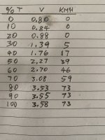
I transcribed the readings from video above (battery at 73.4V). With higher battery voltage, throttle voltage at rest is a little higher at 0.80 V. Top speed increased by 3 KmH. Rain today- no test rides.
larsb
Minor legend
I'd try to single out the issue by removing all but the stuff needed for riding, like brake sensors, buttons and anything else that could cause controller errors. I've had intermittent issues like yours with a throttle wire that i strapped too short and hard to the frame, wire broke and shorted during riding after about a year, causing hickups similar to yours. I've also had similar issues caused by motor hall sensors that were starting to malfunction intermittently - so root cause could be many things.

TommyCat
Power poster
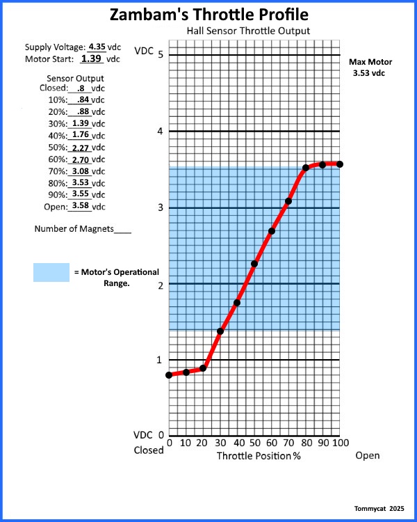
On the way back from a 6 mile ride, throttle acted up again. I was exiting a parking lot to the street, slowed down a bit then gave throttle when there's no response from the motor. As I was rolling down the street, I increased throttle to max, saw the DMM throttle voltage max out but no motor response. While holding the throttle at max, I worked both brake levers with no change, still no motor response. Rolled to a stop, worked the throttle up and down, throttle voltage was changing relative to throttle position, still no motor response. Finally backed throttle all the way to its stop, then forward and rode home.
This is not the OE throttle but behavior is the same. I want to put the OE throttle back (currently lashed to the moped rails where the 3 speed level switch is needed to run the moped).
TommyCat what do you think I should try next? Buy a new controller?
This is not the OE throttle but behavior is the same. I want to put the OE throttle back (currently lashed to the moped rails where the 3 speed level switch is needed to run the moped).
TommyCat what do you think I should try next? Buy a new controller?
TommyCat
Power poster
TommyCat what do you think I should try next? Buy a new controller?
This has always been my first path to pursue...The goal is to get it stuck in a faulted position. I.E. When the fault occurs FREEZE your throttle hand in the position it's in and keep the motor stuck off. Resist the temptation to respond to automatically resetting it, do not allow the throttle to return to the home position! Do NOT use the brake at this time if possible...
Hold it there, walk the bike to a safe spot and lift the drive wheel off the ground with the stand.
After achieving as good and safe a testing position as possible, always keeping the throttle twisted. Now you can lift the seat and check for the tattle-tail flashing controller error code hopefully set.
You have proven that the brake will not reset the issue.
If you can't keep the throttle in stuck position by hand... tape it there. Or use any method that would not fail to keep it in the same position. Park the bike front tire up against a tree or building if you think that would be safer. Pop the seat and check that light!
As always, your safety comes first, only do it if you are comfortable with the procedure and you are sure the motor won't start. This is just the course that I would take.
I put the OE throttle back. I suspect the controller's throttle circuitry became flaky when I hooked up 24S LFP battery (81V) to it where the instrument panel powered up but the throttle would not spin the wheel (on center stand).
I have a controller from when the moped was a few weeks old when the speedo and odometer display stopped working and was replaced with a new one. I just installed that controller which only saw 64V (SLA battery). I'll be riding around with no speedo or odo. Will see if the throttle issue goes away or not.
I have a controller from when the moped was a few weeks old when the speedo and odometer display stopped working and was replaced with a new one. I just installed that controller which only saw 64V (SLA battery). I'll be riding around with no speedo or odo. Will see if the throttle issue goes away or not.
I was hoping the new controller with no speedo wouldn't have this throttle problem but it behaves exactly the same way. Happened twice today. I did not have the DMM hooked up nor did I have tape for the throttle (will carry some next ride).
Yesterday, I practiced taping the throttle to hold position, put scooter on center stand, pop seat to look at LED.
Just got back from a ride where it happened with the OE throttle. LED on conroller not blinking. Brake light not on. I'll check that again next time it happens.
Just got back from a ride where it happened with the OE throttle. LED on conroller not blinking. Brake light not on. I'll check that again next time it happens.
TommyCat
Power poster
Zambam, I salute and cheer on your persistence! Just when I thought no one could be as stubborn as I am. 
Even changing the controller with no better result comes as a bit of a surprise.
I'm intrigued with you mentioning the brake lights, do you have a high type of system where they come on with the brake applied?
Just to stay on track... you have NEVER seen the throttle voltage go below .8 or above 3.6 vdc. Is this accurate?
Even changing the controller with no better result comes as a bit of a surprise.
I'm intrigued with you mentioning the brake lights, do you have a high type of system where they come on with the brake applied?
Just to stay on track... you have NEVER seen the throttle voltage go below .8 or above 3.6 vdc. Is this accurate?
I'd really like to find a cure. I can live with it the way it is but if it gets worse it could become dicy when I need power and there isn't any.Zambam, I salute and cheer on your persistence! Just when I thought no one could be as stubborn as I am.
I'm not sure but according to the link you found for my controller it is "high active 0-12V". When I swap the controller back to the one with speedo /odo, I will buzz out the brake signal and wire up an LED across it so I can observe what it's doing when throttle acts up again.I'm intrigued with you mentioning the brake lights, do you have a high type of system where they come on with the brake applied?
The brake signal could go as low as around 0.79 V depending on where the return spring lands the throttle.Just to stay on track... you have NEVER seen the throttle voltage go below .8 or above 3.6 vdc. Is this accurate?
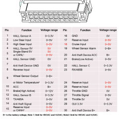
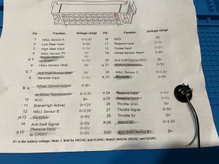
edit #1: attached screenshot of 30 pin controller connector pinout.
pin 11 is brake (high active)
pin 21 is brake (low active)
edit #2:
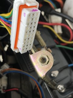
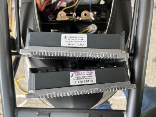
Installed the controller with working speedo/ odo.
Pins 5,7,9,13,15,21,23,24,25,29,30 are not used (no contacts in the harness connector), so only brake high active +12V.
I wired up a bight LED across it.
Last edited:
TommyCat
Power poster
I'd really like to find a cure.
BTW good job on getting a look at the error code light! Disappointing, but I’d still check again if the opportunity presents itself.
Nice detective work on the brake application. Usually high brake is used when the tail light is lit when braking. This is not the case? But your LED install will tell you if you have a sticking brake switch…
Seems to be a bit of deja vu as we have been over this topic or possibility before. Some recommend just disconnecting the brake switch connections whist troubleshooting if possible. When the throttle was held in the system locked out position. You did try the brakes with no change. Perhaps by flicking the brake lever or being more aggressive with the application of the brake switch would help?
For your consideration…
Another recommendation at this time would be to add a bit of resistance to the throttle’s ground wire.
This will raise the home voltage, and have a couple benefits. One, it will remove some dead zone at the beginning of your throttle’s rotation. And more importantly perhaps keep from tripping a possible low throttle voltage cut-out.
Now we could do some testing with a pot and see EXACTLY where the cut-outs are located at. But you might be all tested out.
But the resistor would be easier.. your choice.
A 50 ohm 1/4 watt resistor would get the low low end starting point out of the basement. But if you have a trim pot you could dial it in precisely.
You want to get the throttle signal output at the home position to about 1.2vdc.
Caution: you must do a good secure and proper job of it, as loss of ground to the hall sensor will make the output go high!
Test well on the stand before use. See the throttle thread for other safety precautions and other tips…
Just a thought.
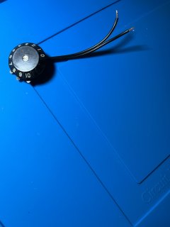
I found a pot that I checked can vary smoothly from 0 to 9k ohm. Do I cut the wire at pin 26 and wire the pot in series?But if you have a trim pot you could dial it in precisely.
Un-used pins have an "x" next to them. Which signal do you think is the speedo/ odo? I'd like to fix the controller with the broken speedo/ odo.
Last edited:
For sure will check again.BTW good job on getting a look at the error code light! Disappointing, but I’d still check again if the opportunity presents itself.
True, tail light lit when braking (also cut power to motor)Usually high brake is used when the tail light is lit when braking.
Last edited:
TommyCat
Power poster
If that ground ONLY goes to the throttle, that is a possibility. I would put it in a location with the easiest access, and less disruption of existing wiring… your call.I found a pot that I checked can vary smoothly from 0 to 9k ohm. Do I cut the wire at pin 26 and wire the pot in series?
See modification #1 in this post for details…
Guide to Hall Sensor Throttle operation, testing, and modification. - Electricbike.com Ebike Forum
Check connections at pin #27 while your in there. Make sure that throttle signal is making it into the controller without problem.
My best guess would be #17, one of the low voltage reserved pins. Any chance of chasing the wire?Which signal do you think is the speedo/ odo?
Not having programming access sure is tough.
Pin 26 (throttle ground) on the controller connector is the easiest, access wise. Remove 2 bolts that hold the seat frame down, swing it up on its hinge and the connector is right there. Less than 30 seconds.If that ground ONLY goes to the throttle, that is a possibility. I would put it in a location with the easiest access, and less disruption of existing wiring… your call.
See modification #1 in this post for details…
Guide to Hall Sensor Throttle operation, testing, and modification. - Electricbike.com Ebike Forum
Check connections at pin #27 while your in there. Make sure that throttle signal is making it into the controller without problem.
I have previously buzzed out pins 26,27,28 up to the throttle itself.
I'll try chasing the wire. It should go to some kind of speed sensor?My best guess would be #17, one of the low voltage reserved pins. Any chance of chasing the wire?
AI overview:
"The speed sensor on a moped scooter is typically located on the wheel hub or within the motor. Some scooters use a speed sensor mounted on the wheel, while others detect speed via Hall sensors within the motor. Direct-drive motors often use Hall sensors in place of a separate speed sensor. "
How do I tell if I have direct-drive motor or not? On center stand, I can spin the rear wheel forward/ backwards easily w/o much resistance. Does that indicate anything?
TommyCat
Power poster
Was my first thought, but AI has good points too.I'll try chasing the wire. It should go to some kind of speed sensor?
Count the number of wires in the motor’s hall sensor connector if possible. Anything over 5 could be a speed sensor, or a temperature sensor. Typically a white wire.
Then again it could be using a motor hall pulse.
Sounds like a direct drive, especially with a controller with reverse.How do I tell if I have direct-drive motor or not?
My moped/ scooter does have reverse, which I never use and had forgotten about!Sounds like a direct drive, especially with a controller with reverse.
per AI overview:
"Generally, geared hub motors cannot be run in reverse, at least not to propel the vehicle forward or backward. This is due to the freewheel mechanism inside the motor, which allows the wheel to spin freely when the motor is not engaged, especially when rotating backward. When a geared hub motor is turned backward, the freewheel engages, and instead of driving the wheel, it spins the motor's internal gears, preventing reverse propulsion. "
Installed 9k pot (set to around 60 ohms in video), DMM across pins 27 throttle signal and pin 26 throttle ground.
With pot set to 60 ohms, DMM reads 0.843 V throttle at rest, wheel starts moving at 30% throttle, max spd 72 kph.
With pot set to 9 kohm, DMM reads 0.515 V throttle at rest, wheel starts moving at 50% throttle, max spd 51 kph.
With pot set to 60 ohms, DMM reads 0.843 V throttle at rest, wheel starts moving at 30% throttle, max spd 72 kph.
With pot set to 9 kohm, DMM reads 0.515 V throttle at rest, wheel starts moving at 50% throttle, max spd 51 kph.
TommyCat
Power poster
Sorry, but according to those voltage readings something must be wrong.
You just use one end of the pot connection and wiper connection in series with the ground wire going to the throttle.
Verify the resistances your getting before installation.
Make sure you start with the resistance at the least amount, and tune the home voltage output from there.
It should not affect the throttle’s WOT voltage output at all.
That thread link includes a nice wiring diagram to make it perfectly clear. Please take advantage of it.
You just use one end of the pot connection and wiper connection in series with the ground wire going to the throttle.
Verify the resistances your getting before installation.
Make sure you start with the resistance at the least amount, and tune the home voltage output from there.
It should not affect the throttle’s WOT voltage output at all.
That thread link includes a nice wiring diagram to make it perfectly clear. Please take advantage of it.
Yeah, I said I was going to do one thing and did another! I cut the throttle signal wire the first time!
Fixed now. With pot set to 50 ohm, throttle V = 1.1 V . Throttle engages quicker (@ around 10%). I backed it off to 1.0 V (20%). Drizzling here so no test ride.
Fixed now. With pot set to 50 ohm, throttle V = 1.1 V . Throttle engages quicker (@ around 10%). I backed it off to 1.0 V (20%). Drizzling here so no test ride.
Similar threads

- Question
- Replies
- 6
- Views
- 1,215

- Replies
- 50
- Views
- 21,172

- Replies
- 11
- Views
- 2,580
- Replies
- 15
- Views
- 3,739
