TSDZ2 EBike wireless standard (like Specialized Turbo Levo) - OpenSource

casainho said:
If you can, please try latest SDCC version. This bug is so strange...

I've just submitted a pull request for a few minor changes. It also 'works around' the assist level 3 problem by changing the way errors are counted. Even so for now it's recommended to avoid using any assist factor of 0.028 if you aren't using the temperature sensor. If for whatever reason you insist on using 0.028 for assist factor - then change the corresponding startup boost factor to something other than 0.028 and you'll be ok.

I also tested at 9600bps just in case - no change. One packet fails CRC - why only when the packet from the wireless controller contains the magic values I do not know. Once that packet fails CRC - there appear to be about 11 bytes that follow - and each causes an error because they are not 'start packet'.

I use the latest SDCC 4.0.7
 
Filippods said:
i'm trying to find a solution that fits with what you told:
-Integrated VLCD5 keypad
-Visible RGB led
-Suitable to 2032 battery case
-With brake connectors
-Removable (find connectors is the hardest thing)
Do not make an impossible problem, simplify:
- use the VLCD5 keypad (with space for the 6 wires)
- visible RGB LED
- space for 2032 and wires
- hole for output of a cable with 2 wires, to externally connect to brake sensors
- forget the idea of removable, just make as the original keypad or similar

I guess is hard to make all this, as the user will need to have space to accommodate the wires and will need to assembly - it should not be impossible to assembly :)
 
rananna said:
What 3D printer would you recommend for printing the remote control with the required accuracy ?
There are so many to choose from on the market.
I use the chinese Creality CR 10S Pro 3D Printer - good quality, really cheap for the quality. I was very fast to assembly, maybe 2 or 3 steps only, I just put the usdcard with the printing file and hit print, and It works very well - I just print in PLA, no advanced materials. The automatic calibration is a must!

I print with 0.2mm layer but I guess it could go to 0.1mm layer for even better quality but would take much more time to print.

I did not tweaking or advanced configuration at all, it is running with original Firmware and I use the Cura software on the PC to generate the 3d print files guide. I even collaborated a bit with initial Open Source RepRap 3d printers, about 11 years ago... Now the technology is so good and cheap... :)
 
casainho said:
I print with 0.2mm layer but I guess it could go to 0.1mm layer for even better quality but would take much more time to print.

Min layer height for mechanical parts is 0.2, 0.1 has less strenght.
 
casainho said:
- hole for output of a cable with 2 wires, to externally connect to brake sensors
- forget the idea of removable, just make as the original keypad or similar

I guess is hard to make all this, as the user will need to have space to accommodate the wires and will need to assembly - it should not be impossible to assembly :)

I'm working on it!
 
casainho said:
If you can, please try latest SDCC version. This bug is so strange...

Ok - I'm not sure anyone is still interested - but just in case - here's some more information on what actually happens when the problem occurs - why it happens is still a mystery...

Below 15 bytes of hex shows the packet that the wireless controller is transmitting. This is the 'bad frame'!

Really odd thing about the 'bad frame' is that the values to the rest of the motor controller code seem immaterial - it's that sequence of bytes being received by the UART that seems to trigger it. If I comment out the code that reads those variables from the frame to pass to the rest of the motor controller - nothing changes!

First three bytes indicate it's a packet from the wireless controller (0x59), it's 0x0D bytes long (excluding CRC) and of type 0x02 (periodic). Next 10 bytes are control data - assist levels etc. and the last two bytes 59 9F are the CRC16.

59 0D 02 1C 00 00 3C 1C 00 63 00 00 4B 59 9F

This trace shows the first 30 bytes of the RX buffer each cycle as the problem occurs - I echo out the RX buffer in a debug frame each cycle along with a host of other data that I've not included here (various counters, timers etc.).

First line is the packet again for comparison. 2nd and subsequent lines are the RX buffer. We can see that the packet arrives fine in the first 15 bytes of the buffer the first cycle. 2nd cycle it's corrupted - the 2nd byte (length field) is now 0x9F. This causes the CRC to fail for that packet as both the data is wrong - plus the CRC uses 0x9F as the length not 0x0D.

Once the length corruption seems to establish itself (2nd byte 0x9F) - this also causes the UART receiver loop/state machine to receive frames way too big and with a wrong frame type (0x59) - so no frames can be interpreted correctly. This is also what causes the bytes after the buffer to get overwritten - eventually there's a complete frame in memory just after the original frame.

In my test code - both the rx and tx buffers are 256 but normally the RX buffer is only 88 bytes so this does look like it would cause memory corruption to other data following the RX buffer since the code only uses the packet length to control the amount of bytes received it doesn't check buffer length. That's a side issue though.

It might be a coincidence that the corruption being written also happens to be one of the CRC16 bytes - but it looks like something somewhere it writing stuff in the wrong place...

So that's what I can see so far - wanted to write it up more to see if something suddenly came to mind.... Anyone with any bright ideas - gratefully received.

Code:
59 0D 02 1C 00 00 3C 1C 00 63 00 00 4B 59 9F
59 0D 02 1C 00 00 3C 1C 00 63 00 00 4B 59 9F 00 9D 00 14 00 CF 00 14 00 E6 00 15 00 F1 00
59 9F 02 1C 00 00 3C 1C 00 63 00 00 4B 59 9F 00 9D 00 14 00 CF 00 14 00 E6 00 15 00 F1 00 
59 9F 59 0D 02 1C 00 00 3C 1C 00 63 00 00 4B 59 9F 00 14 00 CF 00 14 00 E6 00 15 00 F1 00 
59 9F 59 0D 02 1C 00 00 3C 1C 00 63 00 00 4B 59 9F 59 0D 02 1C 00 00 3C 1C 00 63 00 00 4B 
59 0D 02 1C 00 1C 00 00 3C 1C 00 63 00 00 4B 59 9F 59 0D 02 1C 00 00 3C 1C 00 63 00 00 4B
 
Hello casainho, do you remember me? I have been following this project from the start. I have all the parts for it. I have problems flashing the bootloader under Windows. Can you please make the description for a layperson! Thanks in advance.

Another question. I only want to use the Garmin Edge 1030 plus as a control unit. How can I turn on the system there?
 
casainho said:
This bug is so strange...
Following on from the last info dump post.

Ok I suspect this has always been a problem - if I slow down the packets from the wireless controller even slightly - for example so they are sent every 60mS - the problem goes away! 8) So the nrf code is likely spinning faster than the 850/860c code is my guess. Since the motor controller UART code doesn't buffer things very well - and it tends to throw away data when it gets out of sync - can take a while to get back in sync.

I'll have a look at reworking the UART code a little - so that it buffers all input outside of the packet state machine (and keeps the state machine out of the ISR) - and then state machine can process the data from the buffer. Think that may solve it.

Ignore my pull request - I'll do a new one once I've tried and tested this - and hopefully not include .gitignore next time!
 
casainho said:
This bug is so strange...


Ok - this is the a workaround but next post is the proper fix I believe. Change the cycle time to 75mS for rt_processing() up from 50mS. 60mS worked with my test code - but didn't when I rolled back all my test changes.

Code:
static void main_timer_timeout(void *p_context)
{
  UNUSED_PARAMETER(p_context);

  main_ticks++;

  if (main_ticks % (1000 / MSEC_PER_TICK) == 0)
    ui32_seconds_since_startup++;

  if ((main_ticks % (75 / MSEC_PER_TICK) == 0) && // every 50ms
      m_rt_processing_stop == false)
    rt_processing();
}
 
Ok - real progress! Implementing a ring buffer - and putting the wireless controller back to 50mS - and it's all nice and stable!

I'll have more of a test - but this does seem to make the comms loop a lot smoother too!

Code:
// UART
#define UART_RECEIVE_RINGBUFFER_SIZE   256
volatile uint8_t ui8_rx_ringbuffer[UART_RECEIVE_RINGBUFFER_SIZE];
volatile uint8_t ui8_rx_ringbuffer_read_index = 0;
volatile uint8_t ui8_rx_ringbuffer_write_index = 0;

void ebike_app_controller(void)
{
  throttle_read();
  torque_sensor_read();
  read_pas_cadence();
  calc_pedal_force_and_torque();
  calc_wheel_speed();
  calc_motor_temperature();
  ebike_control_motor();
  packet_assembler(); // New to process rx ringbuffer and assemble packets
  communications_controller();
  check_system();
}

...

// Read the input buffer and assemble data as a package, finally, signal that we have a package to process (on main slow loop)
static void packet_assembler(void)
{
  if (ui8_rx_ringbuffer_read_index!=ui8_rx_ringbuffer_write_index)
  {
    if (ui8_received_package_flag == 0) // only when package were previously processed
    {
      while ((ui8_rx_ringbuffer_read_index+1) != (ui8_rx_ringbuffer_write_index))
      {
        ui8_byte_received = ui8_rx_ringbuffer[ui8_rx_ringbuffer_read_index++];
        
        switch (ui8_state_machine)
        {
          case 0:
          if (ui8_byte_received == 0x59) { // see if we get start package byte
            ui8_rx_buffer[0] = ui8_byte_received;
            ui8_state_machine = 1;
          }
          else
            ui8_state_machine = 0;
          break;

          case 1:
            ui8_rx_buffer[1] = ui8_byte_received;
            ui8_rx_len = ui8_byte_received;
            ui8_state_machine = 2;
          break;

          case 2:
          ui8_rx_buffer[ui8_rx_cnt + 2] = ui8_byte_received;
          ++ui8_rx_cnt;

          if (ui8_rx_cnt >= ui8_rx_len)
          {
            ui8_rx_cnt = 0;
            ui8_state_machine = 0;
            ui8_received_package_flag = 1; // signal that we have a full package to be processed
          }
          break;

          default:
          break;
        }
      }
    }
  }
}


// This is the interrupt that happens when UART2 receives data. We need it to be the fastest possible and so
// we do: receive every byte and feed into ringbuffer for the packet assembly routine to consume.

void UART2_RX_IRQHandler(void) __interrupt(UART2_RX_IRQHANDLER)
{
  if (UART2_GetFlagStatus(UART2_FLAG_RXNE) == SET)
  {
    UART2->SR &= (uint8_t)~(UART2_FLAG_RXNE); // this may be redundant

    if ((ui8_rx_ringbuffer_write_index +1)!=ui8_rx_ringbuffer_read_index) 
    		ui8_rx_ringbuffer[ui8_rx_ringbuffer_write_index++] = UART2_ReceiveData8();
    //else Buffer is full! What to do... Just drop data...
  
  }
}
 
beemac said:
Ok - real progress! Implementing a ring buffer - and putting the wireless controller back to 50mS - and it's all nice and stable!

I'll have more of a test - but this does seem to make the comms loop a lot smoother too!

Code:
// UART
#define UART_RECEIVE_RINGBUFFER_SIZE   256
volatile uint8_t ui8_rx_ringbuffer[UART_RECEIVE_RINGBUFFER_SIZE];
volatile uint8_t ui8_rx_ringbuffer_read_index = 0;
volatile uint8_t ui8_rx_ringbuffer_write_index = 0;

void ebike_app_controller(void)
{
  throttle_read();
  torque_sensor_read();
  read_pas_cadence();
  calc_pedal_force_and_torque();
  calc_wheel_speed();
  calc_motor_temperature();
  ebike_control_motor();
  packet_assembler(); // New to process rx ringbuffer and assemble packets
  communications_controller();
  check_system();
}

...

// Read the input buffer and assemble data as a package, finally, signal that we have a package to process (on main slow loop)
static void packet_assembler(void)
{
  if (ui8_rx_ringbuffer_read_index!=ui8_rx_ringbuffer_write_index)
  {
    if (ui8_received_package_flag == 0) // only when package were previously processed
    {
      while ((ui8_rx_ringbuffer_read_index+1) != (ui8_rx_ringbuffer_write_index))
      {
        ui8_byte_received = ui8_rx_ringbuffer[ui8_rx_ringbuffer_read_index++];
        
        switch (ui8_state_machine)
        {
          case 0:
          if (ui8_byte_received == 0x59) { // see if we get start package byte
            ui8_rx_buffer[0] = ui8_byte_received;
            ui8_state_machine = 1;
          }
          else
            ui8_state_machine = 0;
          break;

          case 1:
            ui8_rx_buffer[1] = ui8_byte_received;
            ui8_rx_len = ui8_byte_received;
            ui8_state_machine = 2;
          break;

          case 2:
          ui8_rx_buffer[ui8_rx_cnt + 2] = ui8_byte_received;
          ++ui8_rx_cnt;

          if (ui8_rx_cnt >= ui8_rx_len)
          {
            ui8_rx_cnt = 0;
            ui8_state_machine = 0;
            ui8_received_package_flag = 1; // signal that we have a full package to be processed
          }
          break;

          default:
          break;
        }
      }
    }
  }
}


// This is the interrupt that happens when UART2 receives data. We need it to be the fastest possible and so
// we do: receive every byte and feed into ringbuffer for the packet assembly routine to consume.

void UART2_RX_IRQHandler(void) __interrupt(UART2_RX_IRQHANDLER)
{
  if (UART2_GetFlagStatus(UART2_FLAG_RXNE) == SET)
  {
    UART2->SR &= (uint8_t)~(UART2_FLAG_RXNE); // this may be redundant

    if ((ui8_rx_ringbuffer_write_index +1)!=ui8_rx_ringbuffer_read_index) 
    		ui8_rx_ringbuffer[ui8_rx_ringbuffer_write_index++] = UART2_ReceiveData8();
    //else Buffer is full! What to do... Just drop data...
  
  }
}
Great bit of detective work!
Thanks for tracking this down.
Very subtle bug!
 
rananna said:
Great bit of detective work!
Thanks for tracking this down.
Very subtle bug!

Thanks, yes it's been fun and a bit frustrating - but good to get back to playing with code that runs without an OS or layers of runtimes in between.

My code at the moment has issues - it works right after flashing - but once it disconnects it won't restart until reflashing - I don't think my buffer is wrapping as expected and overwriting stuff!

I think the compiler is doing things I didn't expect. Looking at the assembler - if I'm reading this correctly it's loading my uint8_t index into the low byte of X - and then doing an incw on it. I expected that if i did ++ on a uint8 that's at 255 it would roll over to 0.. This adds 1 to the 16 bit word and uses that for the index and overflows past the end of the array... :shock:

I would hope that when we specify uint8 the compiler would use a more appropriate register... like an 8 bit one!

edit: just need a few more casts - and the compiler is behaving!

Code:
;	ebike_app.c: 1577: if ((ui8_rx_ringbuffer_write_index +1)!=ui8_rx_ringbuffer_read_index) 
	clrw	x
	ld	a, _ui8_rx_ringbuffer_write_index+0
	ld	xl, a
	incw	x
	ldw	(0x01, sp), x
	ld	a, _ui8_rx_ringbuffer_read_index+0
	clrw	x
	ld	xl, a
	cpw	x, (0x01, sp)
	jreq	00102$
	C$ebike_app.c$1578$2_0$622 ==.
 
mallesepp said:
I have problems flashing the bootloader under Windows. Can you please make the description for a layperson! Thanks in advance.
I just went through that.

In short:
- You need ST-Link stick wired to the nRF, connecting stick to USB (Windows drivers needed for ST-Link)
- Download Openocd for Windows and TSDZ2_wireless-bootloader_with_sd-v0.9.0.hex
- Run Openocd: openocd.exe -f stlink.cfg -f nrf52.cfg
- Open a second command shell and run: telnet localhost 4444
- At telnet: program TSDZ2_wireless-bootloader_with_sd-v0.9.0.hex verify
 
Beli said:
mallesepp said:
I have problems flashing the bootloader under Windows. Can you please make the description for a layperson! Thanks in advance.
I just went through that.

In short:
- You need ST-Link stick wired to the nRF, connecting stick to USB (Windows drivers needed for ST-Link)
- Download Openocd for Windows and TSDZ2_wireless-bootloader_with_sd-v0.9.0.hex
- Run Openocd: openocd.exe -f stlink.cfg -f nrf52.cfg
- Open a second command shell and run: telnet localhost 4444
- At telnet: program TSDZ2_wireless-bootloader_with_sd-v0.9.0.hex verify
First draft Instructions are located here:
https://opensourceebike.github.io/build_tsdz2_board.html
Let me know if the instructions work for you.
 
beemac said:
My code at the moment has issues - it works right after flashing - but once motor disconnects it won't restart until power cycle...

I think i'm going insane.... After having quite a productive afternoon yesterday - I've done something to my setup that I can't explain.

Now the motor off function does not work from the app. Motor on works fine if the controller is sending alive packets. When I select 'Motor off' from the android app - it stops sending data to the motor controller and the motor controller stops replying -and that's it. I can't then get it back... I don't see any packet from the nrf to the motor controller telling it to change status - looks like the app/nrf just stops sending periodic packets..

Have to reset or reboot the motor controller to get it sending alive packets again...

I've flashed everything back to the release versions - even tried apk 0.30 again... I've also flashed and tested my spare motor - rather than using the spare controller I've been using for development - and it's the same...

I've reset option bytes and used stvp rather than openocd to program just in case... i've removed the serial tap..

What have I done... :confused: going to do some real work - and then look again later with fresh pair of eyes
 
rananna said:
Beli said:
mallesepp said:
I have problems flashing the bootloader under Windows. Can you please make the description for a layperson! Thanks in advance.
I just went through that.

In short:
- You need ST-Link stick wired to the nRF, connecting stick to USB (Windows drivers needed for ST-Link)
- Download Openocd for Windows and TSDZ2_wireless-bootloader_with_sd-v0.9.0.hex
- Run Openocd: openocd.exe -f stlink.cfg -f nrf52.cfg
- Open a second command shell and run: telnet localhost 4444
- At telnet: program TSDZ2_wireless-bootloader_with_sd-v0.9.0.hex verify
First draft Instructions are located here:
https://opensourceebike.github.io/build_tsdz2_board.html
Let me know if the instructions work for you.

Windows doesn't have telnet client installed by default - appending -c "program TSDZ2_wireless-bootloader_with_sd-v0.9.0.hex verify" does it all in one line and means you don't need to install it.

e.g. openocd.exe -f stlink.cfg -f nrf52.cfg -c "program TSDZ2_wireless-bootloader_with_sd-v0.9.0.hex verify" -c "exit"
 
beemac said:
e.g. openocd.exe -f stlink.cfg -f nrf52.cfg -c "program TSDZ2_wireless-bootloader_with_sd-v0.9.0.hex verify" -c "exit"
Please make a pull request with the changes to the https://opensourceebike.github.io/

And good luck keep the work on finding the issue...!!
 
casainho said:
beemac said:
e.g. openocd.exe -f stlink.cfg -f nrf52.cfg -c "program TSDZ2_wireless-bootloader_with_sd-v0.9.0.hex verify" -c "exit"
Please make a pull request with the changes to the https://opensourceebike.github.io/

And good luck keep the work on finding the issue...!!

I've found and fixed the issue i believe - but I can't fully test it due to motor off stopping working from the app/wireless controller. I've reflashed all fw - motor controller, wireless - going back to bootloader then DFU with all the release binaries and it still persists. I've done mass_erase on the nrf too before flashing. I've cleared cache and data for the app - rebooted my phone and I can connect, turn on motor - but when I turn off motor - everything stops communicating... really puzzling.
 
beemac said:
casainho said:
beemac said:
e.g. openocd.exe -f stlink.cfg -f nrf52.cfg -c "program TSDZ2_wireless-bootloader_with_sd-v0.9.0.hex verify" -c "exit"
Please make a pull request with the changes to the https://opensourceebike.github.io/

And good luck keep the work on finding the issue...!!

I've found and fixed the issue i believe - but I can't fully test it due to motor off stopping working from the app/wireless controller. I've reflashed all fw - motor controller, wireless - going back to bootloader then DFU with all the release binaries and it still persists. I've done mass_erase on the nrf too before flashing. I've cleared cache and data for the app - rebooted my phone and I can connect, turn on motor - but when I turn off motor - everything stops communicating... really puzzling.

@beemac, As you have your hands full trying to nail down the communication problem, I will update the windows instructions for the bootloader.
@casainho, could @beemac's issue be related to TSDZ2_POWER_STATE_OFF_WAIT counter not being decremented for some reason?
 
rananna said:
@beemac, As you have your hands full trying to nail down the communication problem, I will update the windows instructions for the bootloader.
@casainho, could @beemac's issue be related to TSDZ2_POWER_STATE_OFF_WAIT counter not being decremented for some reason?

Thanks - at some point I will start doing some doc updates - got some scripts for building and debugging that might be useful for windows users. I think i've found the reason for my testing woes though - the motor controller must do something like a hard reset at motor off - as it doesn't appear to work with a debugger attached!

I think the source told me that somewhere - I just didn't pay enough attention...

I'll get on with testing later this evening - and hopefully put this serial issue to bed...
 
beemac said:
appending -c "program TSDZ2_wireless-bootloader_with_sd-v0.9.0.hex verify" does it all in one line and means you don't need to install it.

e.g. openocd.exe -f stlink.cfg -f nrf52.cfg -c "program TSDZ2_wireless-bootloader_with_sd-v0.9.0.hex verify" -c "exit"
Interesting. Thanks for that.

And @mallesepp - in case you haven't already installed telnet and still would like to:

Einstellungen -> Apps & Features -> Optionale Features -> Mehr Windows-Funktionen -> Telnet-Client
 
Ok.. . have submitted a pull request - hopefully we're done on assist level 3... I've tested as many scenarios as I can think of - and all seems good. Please take care when testing this update as a) it's my first and b) the code is in the path of every comms between motor and wireless controller!
 
So yesterday I went to ride with my son and our TSDZ2 ebikes are now a very important fitness and happiness machines, since we are "recommend" to stay home due to covid, and is recommended to do sports like walking, running or cycling but only in family.

20210128-154900-2-blur.jpg


[youtube]v_xF5_GnSXQ[/youtube]

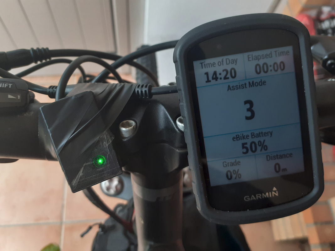
I already removed the 860C display but I decided to keep the remote, which I connected to the remote wireless board. I printed a small case with the hole for the LED, as seen on the video. I had to change the assist level 3 to be different than 0.028 and then everything was ok.

There are small issues on the remote but overall it is working ok. I had to use the mobile app to confirm some things, just to make sure. I have a lot of work to do but I think it will be clear with time what are the most important things for regular usage.

I am very happy and now much more motivated as I am using it :)

I will keep testing the new changes, like the firmware motor controller.
 
casainho said:
So yesterday I went to ride with my son and our TSDZ2 ebikes are now a very important fitness and happiness machines, since we are "recommend" to stay home due to covid, and is recommended to do sports like walking, running or cycling but only in family.

20210128-154900-2-blur.jpg


[youtube]v_xF5_GnSXQ[/youtube]

I already removed the 860C display but I decided to keep the remote, which I connected to the remote wireless board. I printed a small case with the hole for the LED, as seen on the video. I had to change the assist level 3 to be different than 0.028 and then everything was ok.

There are small issues on the remote but overall it is working ok. I had to use the mobile app to confirm some things, just to make sure. I have a lot of work to do but I think it will be clear with time what are the most important things for regular usage.

I am very happy and now much more motivated as I am using it :)

I will keep testing the new changes, like the firmware motor controller.

Being able to do fun things with our family helps keep sanity during the pandemic!

I could not see the box for the remote clearly in the video. Did you happen to try the brakes with the remote? Also, I could not see the led at all. Was it visible through the hole?
casainho said:
There are small issues on the remote but overall it is working ok.
What are the issues?
 
rananna said:
I could not see the box for the remote clearly in the video. Did you happen to try the brakes with the remote? Also, I could not see the led at all. Was it visible through the hole?


I am very busy and I had no free time to install the brakes, maybe this weekend.


rananna said:
casainho said:
There are small issues on the remote but overall it is working ok.
What are the issues?
Things like, the assist level should represent the real assist level on the motor controller, and, on the remote, currently, even if the motor controller is off, the assist level keep changing on the wireless board and I see it changing on the Edge.

There is a delay to see the assist level value on the Edge and on mobile, which is real but still not assist level button pressed should miss, which seems to me it is happening. Can be hard to implement but I think the remote could have a queue of the buttons pressed and store like the last 5 buttons presses and ignore after 5 buttons presses - the queue would need to be a bit more smart like if user press up and then down and then up and up, the ones down and up would be removed. This queue would need to make sure it send one assist level change and have a ok from the other side. This can be complex... but at least the idea is to let user make very quick clicks and never miss anyone.

I think the colors could be red for when no assist level is ready and green when the assist level is ready and changed. I like the blink on the limits. I think the blink is to short for assist level change, maybe could be twice the time, even because it takes a bit of time for assist level change / feel the motor.

I think the focus for the remote should be only to power on/off the motor, change the assist level and change display page. Things like battery SOC are nice but a bit confuse to me in the reality. And I did not had time to understand the blink of long press other then turn on / off the motor.

I tried to change the Edge page but did not worked, I guess I need to read more carefully the instructions of the remote to see how to enable it.

I added to the code a timeout to turn off the remote when there are no ANT communications for 30 seconds. Strange that when I debug it takes about the 30 seconds but with power on the board and not debugging, it takes much more time...
 
Back
Top