TSDZ2 EBike wireless standard (like Specialized Turbo Levo) - OpenSource

casainho said:
And would be important because it would work for every user on this project and not only for the users of your display.
Indeed.
casainho said:
I hope you understand this is a project for wireless. I hope that is the reason why you are here and why you choose to use a board for your display with wireless - I do not see any disadvantage in using the Bluetooth on your board.
First it's good if there are more interested in using the BMS data. The available code (I posted links before) might be a basis for that.
And as I agreed before I know your aim is wireless.
casainho said:
Beli said:
I read that it should be possible for the ESP32 to be both, Bluetooth client and master, at the same time. So connecting the display to the NRF and passing data through the display and making it available for smartphone could be a solution.
That would be a second system between the motor controller and the mobile app. Current there is already a lag on the data sent from the motor to the mobile app because the wireless board is in the middle, adding another board on the middle (of your display) should be avoided.
When using the smartphone beside the small display for configuration (or for displaying or recording additional data) I think the additional lag would be tolerable.

I will have a look if I can code it with Adruino. If so I could give it a trial with the ESP32 setup I already have in use (and mspider's app) .
 
I did some reading. BLE is not really easy to understand...

What we discussed before would be the ability to be Master/Central and Slave/Peripheral at one device at the same time (so the roles for establishing a connection). While there is obviously a (experimental) example for NRF I found nothing like that for ESP32. There are only discussions for both, GATT client and server, at the same time - so the roles for data exchange - and even that is obiously nothing but easy.

So my conclution: I won't go the wireless way for the display.
 
Beli said:
I did some reading. BLE is not really easy to understand...

What we discussed before would be the ability to be Master/Central and Slave/Peripheral at one device at the same time (so the roles for establishing a connection). While there is obviously a (experimental) example for NRF I found nothing like that for ESP32. There are only discussions for both, GATT client and server, at the same time - so the roles for data exchange - and even that is obiously nothing but easy.

So my conclution: I won't go the wireless way for the display.
But you still want to connect to the BMS, so you will need to implement Central. Once you that Central implemented, you can also use it to connect to the TSDZ2 wireless board.

I still think you could separate the implementation fro Central to connect to BMS and TSDZ2 wireless board and use a button to switch to Peripheral to let the mobile app connect to your display and configure it.
 
casainho said:
But you still want to connect to the BMS, so you will need to implement Central. Once you that Central implemented, you can also use it to connect to the TSDZ2 wireless board.
That should be possible.

But what works surprisingly easy: I have a working sketch for connecting to the BMS and displaying its data on my LCD. I added a BLE server and I can connect my smartphone to the display too! So it just works out of the box. However if the connection to the smartphone is closed the connection to the BMS also gets lost.
So there is the danger that the connection between display and motor gets lost. A bike is not an airplane but controlling the bike motor by a wired device still seems securer to me.

Interesting enough it also seems to be possible to connect more then one client (master/central) to the server (slave/peripheral):
https://github.com/nkolban/esp32-snippets/issues/307

It should be possible with the nRF too:
https://embeddedcentric.com/simultaneous-ble-connections/

Concurrent-BLE-connections_Multi_Role.jpg
 
@rananna and other developers,

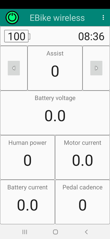
I finally have the Android app finished and I did release V0.3.0: https://github.com/OpenSourceEBike/TSDZ2_wireless/releases/tag/V0.3.0

Because I had troubles in the pins definitions between the different wireless boards, I decided to only use the blue board and so I rewired the previous board with the blue board.
I still have one other board working for firmware development and the firmware works perfectly there. I changed the pins for the blue board and installed using the bootloader, and even testing a few times, the firmware does not work and it is always fast blink the green LED, so, maybe it is fast rebooting.... (note that the bootloader is working as expected, I used the button a few times to start the bootloader - keep button press after pressing the reset button).
Can you please give a look? since the bootloader is working, maybe you can see where are the differences.........

When you get it working, the Android app and this firmware should work very well.


Beli said:
So there is the danger that the connection between display and motor gets lost. A bike is not an airplane but controlling the bike motor by a wired device still seems securer to me.
Using the TSDZ2 wireless board, the connection to the TSDZ2 motor is never lost!! The board is very small and will have a much shorter cable than the regular display cable, so will be easy to secure against the bicycle frame. The risk to break this cable will be much less than using the regular long cable to the display that is on the handle bar.

The user will always be able to turn on / off the TSDZ2 motor and change the assist level, using the button on the wireless board (and get feedback on the RGB LED). If the wireless connection with the mobile phone or with the GPS display is lost, no problem, it will reconnect as soon as possible and nothing will happen - I must say I never saw the wireless connection failing with my cheap mobile phone or with my GPS display!!!

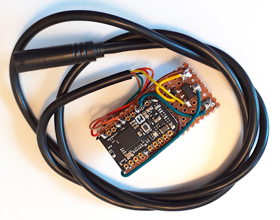
The wireless board is very small and that cable can be way short:

TSDZ2-wireless-board-05.jpg
 
casainho said:
.I changed the pins for the blue board and installed using the bootloader, and even testing a few times, the firmware does not work and it is always fast blink the green LED, so, maybe it is fast rebooting.... (note that the bootloader is working as expected, I used the button a few times to start the bootloader - keep button press after pressing the reset button).
Can you please give a look? since the bootloader is working, maybe you can see where are the differences.........
I am still waiting for the transistors to build the board, and was planning to test then.
It seems that you cannot get the firmware to start on the blue board.
Does the debugger not help to see where it is failing?
What pins did you choose for Rx Tx and motor on?
Was the pin change the only firmware change you made to use the blue board?
 
rananna said:
It seems that you cannot get the firmware to start on the blue board.
Does the debugger not help to see where it is failing?
What pins did you choose for Rx Tx and motor on?
Was the pin change the only firmware change you made to use the blue board?
Maybe you can start building your board without the mosfets, let the space for them there and solder them later. You can see the firmware working and mobile app working, only the motor will not turn on.

The bootloader does not enable any LED, right? and that green LED must be the firmware, right?

I was not able yet to debug on this board... it will take me some days...

Yes, was only pin change - please see my last commit where I did that changes.

I did this connections and changes to pin code:

Wireless_eBike_V1.png
 
casainho said:
The bootloader does not enable any LED, right? and that green LED must be the firmware, right?
Yes the bootloader does not enable any leds.
If this is not the rgb led, but only the green led on the other side of the board, then I believe it can turn only turn on when told to do so by firmware.
This could happen if the gpio port for the green led is accessed by the firmware. Are you sure the right board definition file (pca10059) is being used by the firmware?
 
rananna said:
casainho said:
The bootloader does not enable any LED, right? and that green LED must be the firmware, right?
Yes the bootloader does not enable any leds.
If this is not the rgb led, but only the green led on the other side of the board, then I believe it can turn only turn on when told to do so by firmware.
This could happen if the gpio port for the green led is accessed by the firmware. Are you sure the right board definition file (pca10059) is being used by the firmware?
That is why would be great if you could verify this things by yourself on your board...
I will try tomorrow this on my board.
 
just checked, green is P6 on the pca 10059 board, which is the Tx pin of the mdk dongle.
It would certainly flash a lot if it was connected to the pca10059 board.
 
casainho said:
That is why would be great if you could verify this things by yourself on your board...
I will try tomorrow this on my board.
I am expecting new dongles today for use with the motor. My existing dongles have all been set up for 3V operation.
I will test tomorrow and let you know how I make out with the new firmware.
 
I had a look at your latest commit.
you commented the following:
Code:
#ASMFLAGS += -DBOARD_CUSTOM -DNRF52840_MDK_USB_DONGLE
but did not add:
Code:
ASMFLAGS += -DBOARD_PCA10059

maybe this caused the issue?
I will check and let you know.
 
rananna said:
I had a look at your latest commit.
you commented the following:
Code:
#ASMFLAGS += -DBOARD_CUSTOM -DNRF52840_MDK_USB_DONGLE
but did not add:
Code:
ASMFLAGS += -DBOARD_PCA10059

maybe this caused the issue?
I will check and let you know.
You were correct and I just corrected that issue with the board defines. The firmware and mobile app works well. I was not able to do a regular bicycle ride but I was able to test a few short starts.
Next I will be riding my bicycle and testing, then I will start documenting like drawing the final schematic - would be nice if you have already the new big mosfet and if it works. This weekend I will finish the basic documentation, like the schematic and pointing to instructions for how to install the bootloader.

Maybe I could also design the basic box and 3D print it.

I updated the release, now there is the firmware OTA file and Android app file: https://github.com/OpenSourceEBike/TSDZ2_wireless/releases/tag/V0.3.0

INSTRUCTIONS
On the TSDZ2 wireless board:
1. install the bootloader following this instructions: https://github.com/OpenSourceEBike/TSDZ2_wireless-bootloader
2. install the firmware file TSDZ2_wireless_ota_update-v0.3.0.zip

On your Android phone:
1. install the TSDZ2_wireless_v0.3.0.apk
 
casainho said:
Next I will be riding my bicycle and testing, then I will start documenting like drawing the final schematic - would be nice if you have already the new big mosfet and if it works. This weekend I will finish the basic documentation, like the schematic and pointing to instructions for how to install the bootloader.
Good news!
I am expecting the transistor today. I will wire it up and start testing on the weekend.
Question- I don't see anywhere in the configurations options of the android app to set the ant ID.
This would be a useful addition as it simplifies the user experience to not have to use the nordic app to set the ID
 
rananna said:
Question- I don't see anywhere in the configurations options of the android app to set the ant ID.
This would be a useful addition as it simplifies the user experience to not have to use the nordic app to set the ID
Yes, there are many things to implement yet but current version should be ok for users as you and me. We need now to go slow and improving each part.

Please write the issues / things to implement here, as they will be many and will be easy to forget: https://github.com/OpenSourceEBike/TSDZ2_wireless/issues

And today I was looking to buy the mosfets from a professional online shop of electronics https://www.rs-online.com/. And the difficulties for end users, like being hard to buy without being a company or pay to much for shipping costs, I also found that is very expensive each component like the mosfets because we need to buy minimum quantities of 50 or 20 units!!! So, I really think is important to use components easily found on Ebay - this information should go to the project page instructions:


casainho said:
1. install the bootloader following this instructions: https://github.com/OpenSourceEBike/TSDZ2_wireless-bootloader

I've built a board using the larger mosfet and nordic blue dongle and starting to test - but can't find the bootloader binary in the repo. Unless I'm being a donkey could you post it please?

The firmware HEX file to flash is "TSDZ2_bootloader_with_sd.hex"
located in github releases.
 
casainho said:
And today I was looking to buy the mosfets from a professional online shop of electronics https://www.rs-online.com/. And the difficulties for end users, like being hard to buy without being a company or pay to much for shipping costs, I also found that is very expensive each component like the mosfets because we need to buy minimum quantities of 50 or 20 units!!! So, I really think is important to use components easily found on Ebay - this information should go to the project page instructions:

I got mine from Farnell UK, not sure how their EU shipping is - especially at the moment - but they sell in single quantities. https://uk.farnell.com/infineon/bsp296nh6327xtsa1/mosfet-n-ch-100v-1-2a-sot-223/dp/2480631?st=bsp296
 
beemac said:
casainho said:
And today I was looking to buy the mosfets from a professional online shop of electronics https://www.rs-online.com/. And the difficulties for end users, like being hard to buy without being a company or pay to much for shipping costs, I also found that is very expensive each component like the mosfets because we need to buy minimum quantities of 50 or 20 units!!! So, I really think is important to use components easily found on Ebay - this information should go to the project page instructions:

I got mine from Farnell UK, not sure how their EU shipping is - especially at the moment - but they sell in single quantities. https://uk.farnell.com/infineon/bsp296nh6327xtsa1/mosfet-n-ch-100v-1-2a-sot-223/dp/2480631?st=bsp296
That was I did mention, I simple can´t buy from Farnell here in Portugal, as a final user, only if I had a company.
 
beemac said:
casainho said:
1. install the bootloader following this instructions: https://github.com/OpenSourceEBike/TSDZ2_wireless-bootloader

I've built a board using the larger mosfet and nordic blue dongle and starting to test - but can't find the bootloader binary in the repo. Unless I'm being a donkey could you post it please?

The firmware HEX file to flash is "TSDZ2_bootloader_with_sd.hex"
located in github releases.
Great!! so here you are helping us -- ok, I built the bootloader and did a release, and updated the instructions page with the link for the releases page: https://github.com/OpenSourceEBike/TSDZ2_wireless-bootloader/blob/main/documentation/ubuntu.md

If possible, please share pictures with us of your board, I still do not have pictures to be able to document. Is also always nice to see how other boards are looking like.
 
@casainho,
I got my transistors today and quickly put together a breadboard to test.
Got the android app to communicate with the motor and turn it on/off.
So far everything seems to be working well on that end.
On issue iI found s that the assist level can be successsfully changed from either the remote or a connected garmin display and the android app updates with the new assist level.
However, if you set the assist level first from the android app, it does not get updated in the garmin device.
I had a quick look at the code, but I do not see the issue with ui_vars that is causing ANT to not get the info on the new assist level.
I created an issue for this and the ANT ID
 
rananna said:
@casainho,
I got my transistors today and quickly put together a breadboard to test.
Got the android app to communicate with the motor and turn it on/off.
So far everything seems to be working well on that end.
On issue iI found s that the assist level can be successsfully changed from either the remote or a connected garmin display and the android app updates with the new assist level.
However, if you set the assist level first from the android app, it does not get updated in the garmin device.
I had a quick look at the code, but I do not see the issue with ui_vars that is causing ANT to not get the info on the new assist level.
I created an issue for this and the ANT ID
Please share pictures of your board, if possible.

I would like first to focus on the mobile app and since it is working, now focus on the remote. The usage of the GPS displays, maybe let it to be improved later, after the remote.

There is so much to do, improve... for instance, the wireless board need to have the button working for power on / off, automatic power off (timeout configuration on mobile app?) at least of the TSDZ2 motor and RGB LED feedback. Then design the 3D printed enclosure.

The remote, can you work on it? it needs at least to turn on/off the motor, and now that you see it working on the mobile app, you replicate it on the remote. And it also needs a good visual feedback on the RGB LED.
And the brakes are very important!!

I will soon build a remote to test, because I will have on my ebike this remote and the TSDZ2 wireless board, and I want to use my EBike as I will remove the 860C display from the ebike.
 
casainho said:
beemac said:
casainho said:
1. install the bootloader following this instructions: https://github.com/OpenSourceEBike/TSDZ2_wireless-bootloader

I've built a board using the larger mosfet and nordic blue dongle and starting to test - but can't find the bootloader binary in the repo. Unless I'm being a donkey could you post it please?

The firmware HEX file to flash is "TSDZ2_bootloader_with_sd.hex"
located in github releases.
Great!! so here you are helping us -- ok, I built the bootloader and did a release, and updated the instructions page with the link for the releases page: https://github.com/OpenSourceEBike/TSDZ2_wireless-bootloader/blob/main/documentation/ubuntu.md

If possible, please share pictures with us of your board, I still do not have pictures to be able to document. Is also always nice to see how other boards are looking like.

Thanks for the bootloader - unfortunately during electrical testing again i'm having issues with mosfets... As before it's the 4140 that I just can't get to switch off. These are a new batch - bought from Farnell. When pin 1 is grounded - all is good, 54v 'full on'. But once I remove the gnd to pin 1 and leave it floating - i get 14-15v. I don't know what it is with me and these bloody mosfets! :)

Out of interest what temp do you have your soldering iron at?

I'll have another look tomorrow...
 
beemac said:
- unfortunately during electrical testing again i'm having issues with mosfets... As before it's the 4140 that I just can't get to switch off. These are a new batch - bought from Farnell. When pin 1 is grounded - all is good, 54v 'full on'. But once I remove the gnd to pin 1 and leave it floating - i get 14-15v. I don't know what it is with me and these bloody mosfets! :)

I am seeing the very same phenomenon with the 4140. The voltage is not zero in off mode. Although it is not high enough to turn on the motor, does anyone know if this will this adversely affect the tsdz2 controller?
 
beemac said:
Thanks for the bootloader - unfortunately during electrical testing again i'm having issues with mosfets... As before it's the 4140 that I just can't get to switch off. These are a new batch - bought from Farnell. When pin 1 is grounded - all is good, 54v 'full on'. But once I remove the gnd to pin 1 and leave it floating - i get 14-15v. I don't know what it is with me and these bloody mosfets! :)

Ok... so looks like my new multimeter is garbage. With my usual one I still get 4.7v through the 4140 when 'off' - but at least that's consistent with the last circuits I made.

I've had a google about and can find others who see similar - what appears to be a leakage voltage through a mosfet when testing with a meter and no load. I'll try putting a load on it and see if that fixes.

Either way I'll give the fw a go now...

Sorry about the picture quality!

DSC_2917.JPG
 
casainho said:
The remote, can you work on it? it needs at least to turn on/off the motor, and now that you see it working on the mobile app, you replicate it on the remote. And it also needs a good visual feedback on the RGB LED.
Yes, I can do this. However, I would like to use ANT only to reduce power requirements and avoid the need for another bluetooth profile in the remote.
I can easily use page 16 for communication of all the power states.
And for visual feedback, the R led can signal not ready, Y led for waiting to get ready and G led for motor ready.
My question to you is how best to send the power on/off command by ANT without using bluetooth and the 255 signal.
 
Back
Top