TSDZ2 EBike wireless standard (like Specialized Turbo Levo) - OpenSource

beemac said:
Unless you want the case to be as small as poss - standardise on one that isn't tiny so people can swap in one that's similar - and doesn't exceed the physical spec?
We can let the design to be easy so the box can be easily increase in 1 or 2 directions.

And the documentation can provide 2 or 3 options for the DC-DC component.

rananna said:
casainho said:
About the remote, I have a difficult that is the battery connection, as I can not solder the wires to the battery, what is the best cheap and small way to make the connection??

I avoid soldering and use a surface mount coin cell holder like this:
https://www.aliexpress.com/item/32791160112.html?spm=a2g0s.9042311.0.0.27424c4dabB17n
I use one of that but it takes so much space compared to the battery and the board itself... I guess I will use just wires and some tape to keep the wires in contact. Maybe a little sponge to make pressure and stack the board + battery, inside of the 3D printed enclosure.
 
casainho said:
I use one of that but it takes so much space compared to the battery and the board itself... I guess I will use just wires and some tape to keep the wires in contact. Maybe a little sponge to make pressure and stack the board + battery, inside of the 3D printed enclosure.
The ones I purchased from ali express are only slightly larger than the battery.
Anyway, another approach I have used in the past is to put the coin cell in a little piece of heat shrink tubing that is only slightly larger than the coin cell, add the wires to either side and then heat shrink for a tight fit. It seems to make a good reliable connection.
 
Updated the schematics and the project page, this time telling that other DC-DCs can be used.

For improvements, please fprk and sumbit a pull request:
https://opensourceebike.github.io/

TSDZ2_wireless-schematic.png


ebike_remote_wireless-schematic.png
 
casainho said:

Did you remove 5v to vbus for bootloader flash? Most stlink adapters have that pin and it's safer and easier than needing to power the board separately i think...

edit: Ok only makes sense to wire flash 5v if you plan to leave the flash connections for later use really - otherwise it doesn't make sense to temporarily connect another 5v source if you have one already... that's your thinking?
 
frenchie said:
I'm a bit confused....is the VLCD5 remote keypad using a different nRF52840 dongle? And is that why it needs its own battery?
Yes and yes.
It is communicating and controlling the nrf52840 board on the TSDZ2 motor. That board is performing the role that the display has in a wired ebike.
The remote control allows for assist changes, power control, garmin page changes, etc.
 
rananna said:
frenchie said:
I'm a bit confused....is the VLCD5 remote keypad using a different nRF52840 dongle? And is that why it needs its own battery?
The remote control allows for assist changes, power control, garmin page changes, etc.
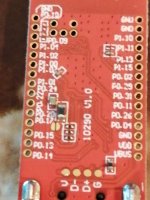
yeah that sounds really good! is it not possible to roll it all up into one board? Then mount it say under the stem like they do with a Di2 controller? I've got a board that I bought for cheap off Aliexpress but the connections are blooming tiny so I wouldn't recommend it...pics for info...and I can't find the SWDIO and SWDCLK connections on it :cry:
IMG_20210122_200354 (copy 1).jpg
IMG_20210122_200518 (copy 1).jpg
 
Filippods said:
Please, could you make a sketch of the remote?
@Filippods,
Sorry, I'm not clear on what you are looking for.
Our current vision is to mount the vlcd5 button controller on the bike handle , and separately mount a very small enclosure on the handlebar containing the nrf52840 and cr2032 battery beside this button controller with the led of the nrf52840 visible to the user. The enclosure would have the wires for the button controller and the brakes running into it. This enclosure and associated handlebar mount is what we need designed.
Could you please elaborate on what you are asking for?
 
frenchie said:
yeah that sounds really good! is it not possible to roll it all up into one board? Then mount it say under the stem like they do with a Di2 controller?
The Di2 group set controller requires 2 sets of wires. One set goes to the brakes/shifters, (which is similar to our use case), however it also requires wires running through the frame to control the shifter. We could of course have only one board on the handlebar with wires going to the motor, but that would kind of defeat the idea of having a totally wireless solution. The wireless communication between the two boards eliminates all wires running up the frame from the motor.
We would also not want it under the stem as the led on the nrf52840 must be visible.
Hope that answers your question.
 
rananna said:
Filippods said:
Please, could you make a sketch of the remote?
@Filippods,
Sorry, I'm not clear on what you are looking for.
Our current vision is to mount the vlcd5 button controller on the bike handle , and separately mount a very small enclosure on the handlebar containing the nrf52840 and cr2032 battery beside this button controller with the led of the nrf52840 visible to the user. The enclosure would have the wires for the button controller and the brakes running into it. This enclosure and associated handlebar mount is what we need designed.
Could you please elaborate on what you are asking for?
sorry for my bad english, now i have understood what do you mean
 
beemac said:
casainho said:

Did you remove 5v to vbus for bootloader flash? Most stlink adapters have that pin and it's safer and easier than needing to power the board separately i think...

edit: Ok only makes sense to wire flash 5v if you plan to leave the flash connections for later use really - otherwise it doesn't make sense to temporarily connect another 5v source if you have one already... that's your thinking?
Well, so I decided to separate the bootloader from the other parts. This means a specific schematic to flash the bootloader and the other schematics will be simple!! Also the bootloader flash process is the same for every board, so, can be only a documentation page for this process.

Here the schematic:

Ebike_wireless_bootloader-schematic.png
 
casainho said:
Well, so I decided to separate the bootloader from the other parts. This means a specific schematic to flash the bootloader and the other schematics will be simple!! Also the bootloader flash process is the same for every board, so, can be only a documentation page for this process.

Here the schematic:

Ebike_wireless_bootloader-schematic.png
I will modify the documentation to describe how to load the bootloader for both the remote and the motor controller.
Perhaps it would be a little less confusing if you removed the swd connection from the remote and motor controller schematics?
 
rananna said:
casainho said:
Well, so I decided to separate the bootloader from the other parts. This means a specific schematic to flash the bootloader and the other schematics will be simple!! Also the bootloader flash process is the same for every board, so, can be only a documentation page for this process.

Here the schematic:

Ebike_wireless_bootloader-schematic.png
I will modify the documentation to describe how to load the bootloader for both the remote and the motor controller.
Perhaps it would be a little less confusing if you removed the swd connection from the remote and motor controller schematics?
Yes, my next step is to simply the other schematics.

At project page, I think we can have a page specifically for the bootloader. Other for the TSDZ2 wireless board, other for the remote. Link from main page to that pages or where makes sense.

Do you want to created the entire bootloader page? If so, do it and send the pull request. Thanks.

I will be building 2 remotes this weekend, one for later be able to debug and the other to install on my EBike. Maybe I will finally remove the 860C display :)

@rananna, if you can also focus on the brakes, that would help me decide to switch already for fully wireless.
 
rananna said:
The wireless communication between the two boards eliminates all wires running up the frame from the motor.
We would also not want it under the stem as the led on the nrf52840 must be visible
ok thanks so do you envisage the 'motor nRF52840' being mounted on the seat tube?
why must the led be visible for the other one? I would have thought once comms are established with your bluetooth device, job done?
what's the plan with the brakes?
cheers!
 
I
casainho said:
rananna said:
casainho said:
Well, so I decided to separate the bootloader from the other parts. This means a specific schematic to flash the bootloader and the other schematics will be simple!! Also the bootloader flash process is the same for every board, so, can be only a documentation page for this process.

Here the schematic:

Ebike_wireless_bootloader-schematic.png
I will modify the documentation to describe how to load the bootloader for both the remote and the motor controller.
Perhaps it would be a little less confusing if you removed the swd connection from the remote and motor controller schematics?
Yes, my next step is to simply the other schematics.

At project page, I think we can have a page specifically for the bootloader. Other for the TSDZ2 wireless board, other for the remote. Link from main page to that pages or where makes sense.

Do you want to created the entire bootloader page? If so, do it and send the pull request. Thanks.

I will be building 2 remotes this weekend, one for later be able to debug and the other to install on my EBike. Maybe I will finally remove the 860C display :)

@rananna, if you can also focus on the brakes, that would help me decide to switch already for fully wireless.
I will work on the brake implementation this weekend.
I will also create the bootloader page.
 
rananna said:
I will work on the brake implementation this weekend.
I will also create the bootloader page.
Thanks and do not forget the idea of simplification for final user, just for simplified instalation, on the project page. For technical documentation and developers, you can link to the repo readme.
 
casainho said:
Well, so I decided to separate the bootloader from the other parts. This means a specific schematic to flash the bootloader and the other schematics will be simple!! Also the bootloader flash process is the same for every board, so, can be only a documentation page for this process.

Here the schematic:

Ebike_wireless_bootloader-schematic.png

Ok got it, makes sense.

I've had some time this afternoon to look at the serial comms. I've written a decoder to interpret the packets being sniffed on the wire - and there seem to be a couple of things going on.

Assist level three packets are sent less frequently - still trying to see why.

But the most puzzling thing I'm seeing - and my first thought is I've done something stupid in my receiver code - but it looks like the crc lags behind the packets regardless of assist level. I get anything up to 30 packets after the data has changed being sent with the old CRC. Then it catches up and the CRCs start validating again...

Here's an example - these are all periodic packets being sent by the motor controller. i'm using a different motor controller than the one installed in the tsdz2 on my bike just fyi.

First two fields -
rXXXX is the received CRC
cXXXX is the CRC i calculate from the packet.
rest of the line is the payload after first byte packet type, 2nd byte packet length etc.

You can see that CRC matches for first three packets - then the 9th byte changes from 05 to 04. There is then a lag whilst the CRC is incorrect for 19 packets - then it catches up...

I've looked at the code the generates the packets and can't see why this might happen - so my focus for now is checking my reciever code to make sure what I'm seeing is really happening. I thought i'd mention it just in case you could see a reason why this happens...

rF5A3:cF5A3 43 1B 02 28 00 00 00 00 1E 05 00 00 00 00 00 00 00 00 01 80 00 00 00 00 00 00 00
rF5A3:c9F2 43 1B 02 28 00 00 00 00 1E 04 00 00 00 00 00 00 00 00 01 80 00 00 00 00 00 00 00
rF5F2:c9F2 43 1B 02 28 00 00 00 00 1E 04 00 00 00 00 00 00 00 00 01 80 00 00 00 00 00 00 00
r9F2:c9F2 43 1B 02 28 00 00 00 00 1E 04 00 00 00 00 00 00 00 00 01 80 00 00 00 00 00 00 00
 
beemac said:
Assist level three packets are sent less frequently - still trying to see why.

Oh and btw - I did a full erase and this is with reflashing everything (including wireless controller) via stlink. Code for all components compiled from latest source.

The error rate is pretty consistent - but in assist level 3 approx 350/s packets are sent - whereas in all other assist modes - about 530/s are sent.

See here - am in assist level 3 - factor set to the bad value of 0.028 - packet rate from motor controller is c.350/s
Once I change the factor to 0.027 - packet rate picks up to 530/s

Errors in last sec : 114. Packets in last sec : 348. Errors per packet 0.3275862 << Assist level 3 factor is 0.028
Errors in last sec : 77. Packets in last sec : 348. Errors per packet 0.22126436
Errors in last sec : 114. Packets in last sec : 348. Errors per packet 0.3275862
Errors in last sec : 152. Packets in last sec : 348. Errors per packet 0.43678162
Errors in last sec : 76. Packets in last sec : 348. Errors per packet 0.21839081
Errors in last sec : 152. Packets in last sec : 348. Errors per packet 0.43678162
Errors in last sec : 95. Packets in last sec : 348. Errors per packet 0.2729885
Errors in last sec : 114. Packets in last sec : 319. Errors per packet 0.35736677
Errors in last sec : 114. Packets in last sec : 348. Errors per packet 0.3275862
Errors in last sec : 76. Packets in last sec : 348. Errors per packet 0.21839081
Errors in last sec : 95. Packets in last sec : 348. Errors per packet 0.2729885
Errors in last sec : 152. Packets in last sec : 522. Errors per packet 0.29118773 << I change the assist level 3 factor to 0.027
Errors in last sec : 153. Packets in last sec : 493. Errors per packet 0.31034482
Errors in last sec : 228. Packets in last sec : 551. Errors per packet 0.41379312
Errors in last sec : 222. Packets in last sec : 543. Errors per packet 0.4088398

Oddly I see the CRC issue in the packets going from the wireless controller too. It catches up much quicker though - in generally 11 packets..


Here's the same test from the wireless controller: Packet rate is consistent regardless of assist level or values - and you can see the 11 packet CRC lag causing errors when i did a change of assist level... so data changed in the packets

Errors in last sec : 0. Packets in last sec : 315. Errors per packet 0
Errors in last sec : 0. Packets in last sec : 300. Errors per packet 0
Errors in last sec : 0. Packets in last sec : 315. Errors per packet 0
Errors in last sec : 0. Packets in last sec : 308. Errors per packet 0
Errors in last sec : 0. Packets in last sec : 307. Errors per packet 0
Errors in last sec : 0. Packets in last sec : 300. Errors per packet 0
Errors in last sec : 0. Packets in last sec : 315. Errors per packet 0
Errors in last sec : 11. Packets in last sec : 300. Errors per packet 0.036666665
Errors in last sec : 0. Packets in last sec : 315. Errors per packet 0
Errors in last sec : 0. Packets in last sec : 300. Errors per packet 0
Errors in last sec : 0. Packets in last sec : 315. Errors per packet 0
Errors in last sec : 0. Packets in last sec : 308. Errors per packet 0

I'm still trying to get gdb debugging working - but sounds like profiling the motor controller code would be helpful. I can get openocd to connect but when I try to start a debug session I get:

Failed to launch OpenOCD GDB Server: Error: spawn openocd.exe ENOENT

If I paste the openocd command it's trying to execute into the shell - it starts just fine... anyone with any ideas - gratefully received! :)


edit: attached the source of the monitor app - it's hardly rocket science on my part - and I've used the code for crc etc. so less likely to be my implementation error but just in case someone else can see anything i've done that would cause the CRC issue to be a false positive.
 

Attachments

  • tsdzmonitor.txt
    5 KB · Views: 12
I updated the schematics:

TSDZ2 wireless board:
TSDZ2_wireless-schematic.png


TSDZ2 wireless remote:
ebike_remote_wireless-schematic.png


beemac said:
But the most puzzling thing I'm seeing - and my first thought is I've done something stupid in my receiver code - but it looks like the crc lags behind the packets regardless of assist level. I get anything up to 30 packets after the data has changed being sent with the old CRC
I hope you get it!!
 
casainho said:
I updated the schematics:

TSDZ2 wireless board:
TSDZ2_wireless-schematic.png


TSDZ2 wireless remote:
ebike_remote_wireless-schematic.png

Ah nice - i particularly like that that the io pins don't conflict between remote and wireless controller anymore for my ultimate aim down the line 8)

beemac said:
But the most puzzling thing I'm seeing - and my first thought is I've done something stupid in my receiver code - but it looks like the crc lags behind the packets regardless of assist level. I get anything up to 30 packets after the data has changed being sent with the old CRC
casainho said:
I hope you get it!!

Going to call it a night soon - but if you have any handy hints about getting openocd profiling/general debugging going in vscode so I can see what's going on in the motor controller when it slows down teh send rate that would really help us pin this down I think.

If what I'm seeing is right - the motor controller is spending a lot of time sending useless packets... can this be the case?!
 
beemac said:
casainho said:
I updated the schematics:

TSDZ2 wireless board:
TSDZ2_wireless-schematic.png


TSDZ2 wireless remote:
ebike_remote_wireless-schematic.png

Ah nice - i particularly like that that the io pins don't conflict between remote and wireless controller anymore for my ultimate aim down the line 8)

beemac said:
But the most puzzling thing I'm seeing - and my first thought is I've done something stupid in my receiver code - but it looks like the crc lags behind the packets regardless of assist level. I get anything up to 30 packets after the data has changed being sent with the old CRC
casainho said:
I hope you get it!!

Going to call it a night soon - but if you have any handy hints about getting openocd profiling/general debugging going in vscode so I can see what's going on in the motor controller when it slows down teh send rate that would really help us pin this down I think.

If what I'm seeing is right - the motor controller is spending a lot of time sending useless packets... can this be the case?!

Ah i've found an issue in my receiver code :oops: CRC is fine! Phew... packet rate should have told me my counters were incorrect - way too high and there was a clue in that the lag was always the packet size plus some. I wasn't resetting the packet_received flag.

Ok - so tomorrow if I have time I'll focus on why the motor controller send rate drops in level 3... that's definitely occurring!
 
beemac said:
Going to call it a night soon - but if you have any handy hints about getting openocd profiling/general debugging going in vscode so I can see what's going on in the motor controller when it slows down teh send rate that would really help us pin this down I think.
I once get the Code Studio and OpenOCD working for the STM8 but I deleted the files by mistake. But it was hard to get it working.

I use Eclipse only for the STM8 but I do not have written notes how to make it working...
 
beemac said:
Ah nice - i particularly like that that the io pins don't conflict between remote and wireless controller anymore for my ultimate aim down the line 8)

There is an overlap on P0.22 where the Brake pin overlaps with the TSDZ2_RX pin.
I also share your vision but I hardly believe that Casainho would agree to re assign the pin to another one that is free and not overlapping like P0.10. In this way we will have brake input and brake output next to each other.

I don’t know what your aim is. Mine is to run the wireless controller with the buttons directly attached to it without the wireless remote. Simple plugin replacement of the currently used Bafang displays. So I can easily switch between the Bafang display or wireless controller in combination with the mobile phone.

I know that this simplifies the complex idea of having a full wireless bike. I would also support that idea in case we did not had already the cables for the rear brake and the shifter running from the rear side of the bike to the handlebar. For people that will never use the Garmin GPS or watch, the remote with the second board and the battery are of no real use.

It could be the case that I am wrong in my last statement. May be with the combined code in a single repository we could have both the remote and the wireless controller running on a single board. And why not a simple display connected to them. Finally this would be something like the dreamed SW102 but with the additional protocol for the Garmin integration.
 
plpetrov said:
beemac said:
Ah nice - i particularly like that that the io pins don't conflict between remote and wireless controller anymore for my ultimate aim down the line 8)

There is an overlap on P0.22 where the Brake pin overlaps with the TSDZ2_RX pin.

Oh no i didn't see that... @casainho and @rananna is there any chance we could move the brake input to p0.10 on the remote? Pretty please ? :)
 
plpetrov said:
There is an overlap on P0.22 where the Brake pin overlaps with the TSDZ2_RX pin.
I also share your vision but I hardly believe that Casainho would agree to re assign the pin to another one that is free and not overlapping like P0.10. In this way we will have brake input and brake output next to each other.

For people that will never use the Garmin GPS or watch, the remote with the second board and the battery are of no real use.
Even there is no need to use a remote at all, everything is optional (only the wireless board is mandatory). You can use the wireless board to change the assist level and turn on/off the system, so, not even need of extra buttons.

There is no issue for us to use that other pin, I will update the schematic tomorrow.
 
Back
Top