ezrider1199 said:
Hi,
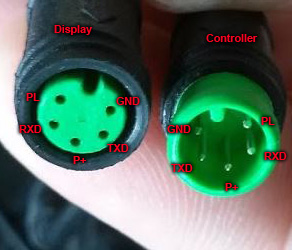
I received a 850c from pswpower and am trying to flash it. I noticed it doesnt fit into my 4-1 cable because it came with a female end so i attempted to put on a new male connector (luckily had a spare). Cut it up and see that the colors are off and the pin positions dont match with what tsdz2 is expecting. So I tried to figure out and match up the pins according to this
.
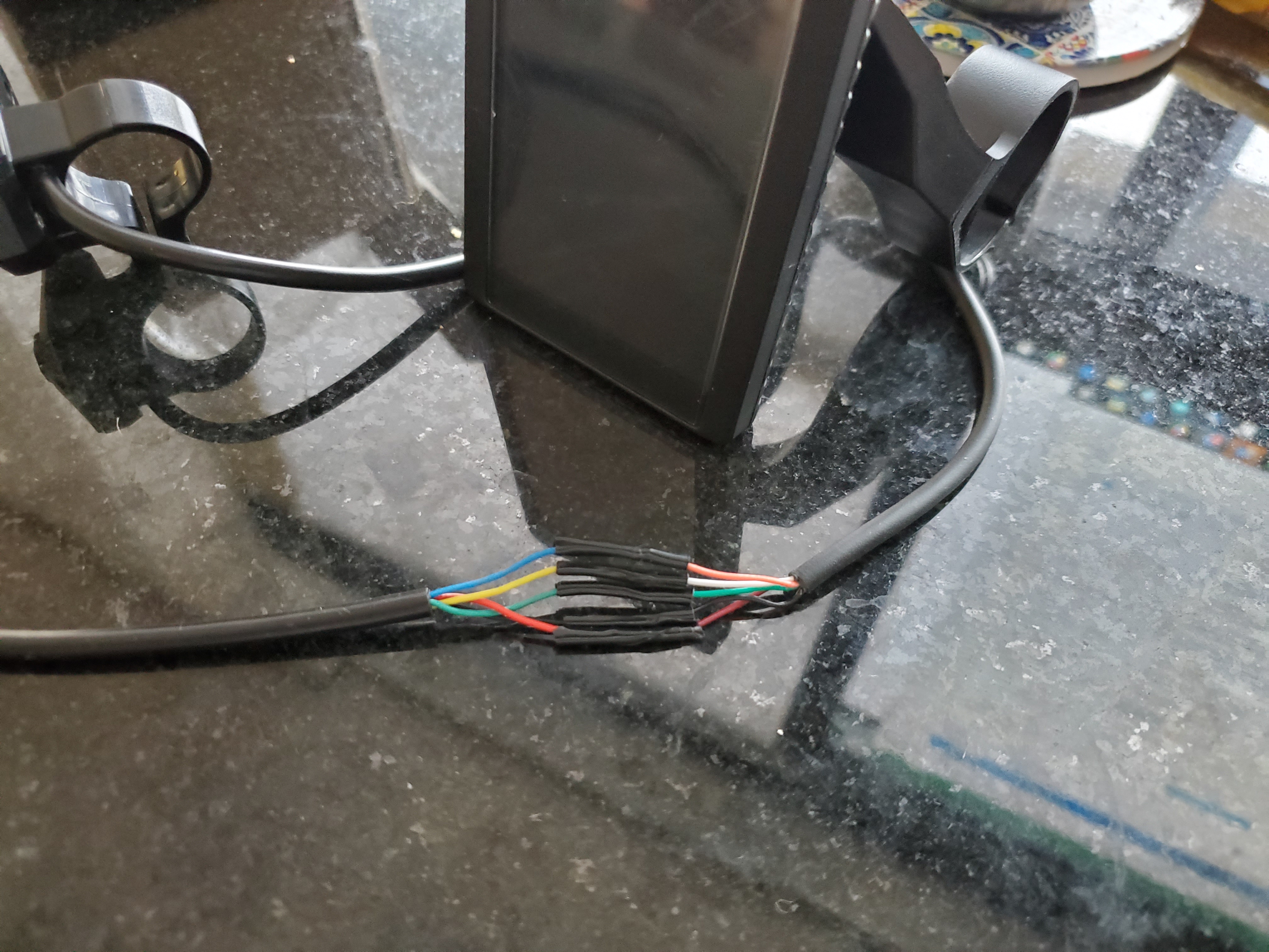
Here's where I am now
.
Currently I am able to plug an unflashed 850c to my controller and see it start up but I can't get it to flash... is there anything i can verify? I assume that because the 850c can startup that my wiring should be ok. The APT program doesn't show much in the way of errors. Thanks
Tsdz2 display --> 850c
Gnd, Black --> black
Batt V+, Red --> purple
Rx, Yellow --> white
Tx, Green --> green
5v, Blue --> orange
izeman said:
redwater said:
VIN - orange
Rx - white <--- Tx from UART
+26-54V - brown
Tx - green <--- Rx from UART
GND - black
Colours from 850C cable ofcourse.
Thanks. And Vin/Orange is same voltage as Brown wire? And for programming, does it need Orange or Brown wire to be powered? It's hard to see from pictures.
Hello everyone,
I too decided to embark on the trail of installing TSDZ2 on my bicycle as reading through the forum it felt like the right motor for my needs
")
Along the way I also decide to install open source firmware together with 850c display.
I'm currently in the process of trying to flash the firmware on 850C using bootloader and a DIY bootloader box as mentioned in TSDZ2_wiki. However i ran into some problems during the process and would like to ask for help
My situation:
I've connected the components for the DIY bootloader box using the guide provided in TSDZ2_wiki:
https://github.com/OpenSource-EBike-fir ... bootloader
After that, I've connected it to my PC and to my 850c display. All seems fine as before installing the firmware I've tried to power on the display it it starts up and shows all the data (current time, voltage (note: it displays 29.8V while being powered from my PC via bootloader box), km/h etc.).
So now I've identified my COM port (COM3), installed the required drivers, and opened the APT burn tools (v1.3) to start the flashing process.
Next up in the APT burn tools window I've selected my COM3 port, opened it, after that I've selected the firmware for 850c display and pushed he update firmware after which the program showed "waiting..." sign.
I've pushed my power button, but the display did not show anything, the flashing did not start and the message in the program kept repeating "waiting...". It seems I can not get the 850c display to flash.
What I've noticed in the program is that while it's waiting on the input from the display the numbers values near "Tx" (at the bottom of APT burn tools window) are constantly changing and increasing, while number near "Rx" stays at "0". Does this mean there is a problem with Rx connection?
I've followed the wire connection diagram in TSDZ2 wiki and the info on how to splice and connect the 5pin extension wire given by user ezrider1199 and later on user izeman in their posts. I've checked multiple times whether all the wires are connected correctly and it seems that everything is as show in the TZDZ2 wiki.
Does anyone else had the issue of display not flashing and has a solution to my situation?
P.S I've got my display from PSPOWER and it sayson the back of dispalay "850c tftgdv2.3clb60 xf2.0" and "V5.2 201909210119".
SOLUTION:
In my case i've tried switching Tx and Rx wires and flash again. To my surprise it worked! Yuppi!
This might no be the case to others, but I'll post my final wiring by colors that I have below:
My 5pin extension wires are connected as follows:
(I've identified wire labels according to this image:
http://i.imgur.com/3GaLDI1.jpg)
5pin extension cable
white wire (I identified it as "RxD") -> USB to UART connection point "RxD"
black wire ("GND") -> DC booster connection point "OUT-" (GND)
green wire ("TxD") -> USB UART connection point "TxD"
red (i guess it's brown"ish") ("P+") -> DC booster connection point "OUT+" (P+)
orange wire -> left it unconnected (just dangling there on the side)
DC booster connection point "IN+" -> USB to UART connection point "5V"
DC booster connection point "IN-" -> USB to UART connection point "GND"
This solution might be specific to my situation therefore I would suggest to try it at own risk and only if all else fails (try rechecking if you identified the connection points correctly and if you connected everything correctly according to TSDZ2 wiki guide).