
You are using an out of date browser. It may not display this or other websites correctly.
You should upgrade or use an alternative browser.
You should upgrade or use an alternative browser.
TSDZ2 mid drive with 860C, 850C or SW102 displays only -- Flexible OpenSource firmware (Casainho code only)
- Thread starter casainho
- Start date
casainho
10 GW
- Joined
- Feb 14, 2011
- Messages
- 6,058
Assist level and start power boost now work as a factor of rider pedal human power
I implemented it and it is so nice to look at LCD3 and see the motor exactly assist you, for instance, 200% of your generated pedal human power, if you did set the assist level to 2.0.
On LCD3 odometer field you can now see:
1. pedal torque (in Nm);
2. pedal energy power (in Watts).
The 1. uses as input the force applied to the pedals (torque sensor signal) and 2. multiplies 1. to pedal cadence. Because of this, the startup power boost assist level scale factor uses 1. and regular assist level scale factor uses 2.
This code is available here: https://github.com/OpenSource-EBike-firmware/TSDZ2-Smart-EBike/pull/47
Soon I hope that EndelessCadence can review/test it and make a new firmware release that includes some nice new developments!!
casainho
10 GW
- Joined
- Feb 14, 2011
- Messages
- 6,058
I really appreciate your work.jbalat said:Just some testing on the inverse ramp factor to reduce lag
[youtube]UXVxzXzJDbc[/youtube]
After your notes and reports, I think I did learn a new things. First, I do not agree that we should just reduce the PWM_DUTY_CYCLE_RAMP_UP_INVERSE_STEP, as I believe it should be worst for the gears and other mechanical parts.
I think it can be done like this:
1. we should implement a current ramp and not a duty_cycle ramp. I think now as duty_cycle representing motor rotor speed and the current representing the torque.
2. implement: current ramp AND PWM_DUTY_CYCLE_RAMP_UP_INVERSE_STEP at a lower value maybe like 10
3. Let´s say we set our target current to 10 amps and the current ramp increases 1 amp per each 0.1 second, so after 1 second the motor ends at 10 amps but the current/torque stress on gears and mechanical parts increase with the ramp from 0 to 10 in 1 second.
4. At the first step on 0.1 second, the current ramp controller will set current to 1 amp and duty-cycle will jump very fast on that 0.1 second to get 1 amp and that should make motor rotate very fast to the desired final speed and engage the gears but using that low current... -- I think the result is what we all would like to have: fast response but not with an abrupt torque!!!
casainho said:I really appreciate your work.
After your notes and reports, I think I did learn a new things. First, I do not agree that we should just reduce the PWM_DUTY_CYCLE_RAMP_UP_INVERSE_STEP, as I believe it should be worst for the gears and other mechanical parts.
I think it can be done like this:
1. we should implement a current ramp and not a duty_cycle ramp. I think now as duty_cycle representing motor rotor speed and the current representing the torque.
2. implement: current ramp AND PWM_DUTY_CYCLE_RAMP_UP_INVERSE_STEP at a lower value maybe like 10
3. Let´s say we set our target current to 10 amps and the current ramp increases 1 amp per each 0.1 second, so after 1 second the motor ends at 10 amps but the current/torque stress on gears and mechanical parts increase with the ramp from 0 to 10 in 1 second.
4. At the first step on 0.1 second, the current ramp controller will set current to 1 amp and duty-cycle will jump very fast on that 0.1 second to get 1 amp and that should make motor rotate very fast to the desired final speed and engage the gears but using that low current... -- I think the result is what we all would like to have: fast response but not with an abrupt torque!!!
sounds good. might also smooth out the startup sequence from standing still since at the moment sometimes it fells like the gears have a hard time
") so many good news today!
so many good news today!jbalat
10 kW
Casainho if you think this will be better then I'm all for it
BTW I am 100% happy with changing the inverse ramp.. If it is putting stress on the components I am not sensing it.
I guess my riding style will change over time to compensate. I always make sure I'm in a low gear when I take off. If I am accidentally in a high gear I will only apply a small amount of pressure to the pedals until I get moving.
This is pretty much what I would do on a non-motorised bike anyway. Some people don't take this care and could damage something. So if your new code helps to solve this then great !!
Looking forward to your human power stuff, sounds exciting. I still recommend we implement the lower value of inverse ramp to eliminate lag in this release until you can get the new ramp code going.
gaber
10 W
gaber said:How have you guys wired in your brake wires? I understand how to do it schematically (thanks to the wiki, but am curious where you’ve spliced them in and what kind of connectors. Looking to capitalize on the group think instead of reinventing the wheel.
Same interest here.. unfortunately the LCD3 lacks of brake ports and I would like to avoid driving the brake cables all the way to the motor where I have to solder the cable from the display anyway.
Thanks casainho if you can add a picture to show where you connected the ebrakes and a brief description (I ordered the bafang magnetic sensors from pswpower yesterday)
stancecoke
1 MW
casainho said:1. we should implement a current ramp and not a duty_cycle ramp.
Why don't you use a PI-controller for the battery current, like we do in the Kunteng project? With this you can adjust the response time very easily with the parameters Gain_P and Gain_I...
Code:
uint32_t PI_control(uint16_t pv, uint16_t setpoint, uint8_t uint_PWM_Enable) {
	float float_p;
	static float float_i;
	static float float_dc = 0;
	float_p = ((float) setpoint - (float) pv) * flt_s_pid_gain_p;
	float_i += ((float) setpoint - (float) pv) * flt_s_pid_gain_i;

	if (float_i > 255)float_i = 255;
	if (float_i < 0)float_i = 0;

	if (float_p + float_i > float_dc + 5) {
		float_dc += 5;
	} else if (float_p + float_i < float_dc - 5) {
		float_dc -= 5;
	} else {
		float_dc = float_p + float_i;
	}

	if (float_dc > 255)float_dc = 255;
	if (float_dc < 0)float_dc = 0;

	return ((uint32_t) (float_dc));
}
regards
stancecoke
casainho
10 GW
- Joined
- Feb 14, 2011
- Messages
- 6,058
I am not a big fan of PI controllers, I prefer the ramp approach. If I find more value over ramp for PI, I will implement it. Do you know an advantage of using a PI controller (for this current controller) over a ramp?stancecoke said:Why don't you use a PI-controller for the battery current, like we do in the Kunteng project? With this you can adjust the response time very easily with the parameters Gain_P and Gain_I...casainho said:1. we should implement a current ramp and not a duty_cycle ramp.
stancecoke
1 MW
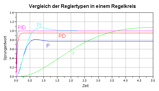
The advantage ist very clear, you get a much faster and more natural response with the PI-control (turquoise green plot).
Your implementation is a pure I-control (light green plot). With our experience, you don't need an extra control in the fast loop.
regards
stancecoke
Your implementation is a pure I-control (light green plot). With our experience, you don't need an extra control in the fast loop.
regards
stancecoke
casainho
10 GW
- Joined
- Feb 14, 2011
- Messages
- 6,058
Ah, I see. But I don´t like that approach having current controller on slow loop, I really prefer it on fast loop and on motor.c. Users are playing on ebike_app.c and that way are not making issues with the current controller, that I think otherwise would result in burned motor controllers.stancecoke said:With our experience, you don't need an extra control in the fast loop.
The current controller on fast loop is faster 1562 times compared on slow loop so I think it does not need a PI controller. What may be missing is that ¨natural response¨, but in reality seems that users may prefer a fast response from the torque at the very first time. Maybe the ¨natural response¨ would be good for speed controller, as I think for speed it should be soft for cutoff on max speed limit.
Well, I think there are other things to improve yet before start experimenting with speed of softness of motor response for torque and or speed. On that time, I will for sure look at your code and graphs
EndlessCadence
100 W
- Joined
- Aug 22, 2018
- Messages
- 217
Fantastic! Keep up the good work! Sure I'll test and release it sooncasainho said:Assist level and start power boost now work as a factor of rider pedal human power
I implemented it and it is so nice to look at LCD3 and see the motor exactly assist you, for instance, 200% of your generated pedal human power, if you did set the assist level to 2.0.
On LCD3 odometer field you can now see:
1. pedal torque (in Nm);
2. pedal energy power (in Watts).
The 1. uses as input the force applied to the pedals (torque sensor signal) and 2. multiplies 1. to pedal cadence. Because of this, the startup power boost assist level scale factor uses 1. and regular assist level scale factor uses 2.
This code is available here: https://github.com/OpenSource-EBike-firmware/TSDZ2-Smart-EBike/pull/47
Soon I hope that EndelessCadence can review/test it and make a new firmware release that includes some nice new developments!!
stancecoke
1 MW
casainho said:But I don´t like that approach having current controller on slow loop
Perhaps you can do a similar log with your implementation, to see if there is any difference in the lag between current target and recent current. My log is with 50Hz slow loop frequency.
regards
stancecoke
Trying to mount the Bafang Gear Shift Sensor, and it seems to work.*
But when connected, the Display gets unreadable dim. I followed the instruction for the hidden break wire sensor to get the necessary 5V - from the programmer pin. But despite of the Bafang Gear Sensor only using 0.01W, it blanks out the display.
Is the power drain to high for this 5V Pin? Is there some recommended spot on the display to get more stable 5V?
(To give the complete picture: Still using a 24V Battery wich at three quarter empty also makes a dim display. But still, the sensor only using 0.01W)
(*it looks like the brake symbol coming up when I move a wire in the sensor, but because of the almost unreadable Display I'm not quiete sure)
casainho
10 GW
- Joined
- Feb 14, 2011
- Messages
- 6,058
I prefer to have current controller on fast loop but it is not about speed. I remember from Dave Wilson videos that for industrial FOC motor control they do PI controller for current on the fast loop, so maybe 100x faster than what you are doing. But I think we do not need the so fast response from our motors (that is why our microcontrollers are so slow and cheap, could not do PI on fast loop) and so I decided to do fast/dirty/bitbang on fast loop instead of slow PI on slow loop.stancecoke said:Perhaps you can do a similar log with you implementation, to see if there is any difference in the lag between current target and recent current. My log is with 50Hz slow loop frequency.casainho said:But I don´t like that approach having current controller on slow loop
Why I do prefer fast/dirty/bitbang than slow PI? because I prefer simple things, and after testing them, they seem to work very well for our needs/application.
Also I like the modularity and isolation I get when having the current control loop on the fast loop, and let slow loop for ebike application only. The isolation means that up to now, users were able to play on slow loop ebike application code but didn´t burned the motor controller, because the fast loop is always working (the only one interrupt on the system -- yes, another different approach we have here but because I want to understand very well what is happening!) and controlling/limiting the max current.
From Dave Wilson videos, I remember that speed control loop can be done at lower frequency than the current loop -- it could be done on slow loop. Dave Wilson talks about cascade PI controllers and also says others have success with only one PID controllers as you seem do be done (??).
When I feel the need for a PID controller, I will jump to it.
casainho
10 GW
- Joined
- Feb 14, 2011
- Messages
- 6,058
With the new data on odometer field, it started to me a mess and so I did this improvements:
The LCD3 is now to start being a mess and I think I will not do much more improvements/changes. I know that it misses data in inches like speed, distance and also misses time of the trip. Other than this, I would say the LCD3 firmware is mostly complete.
Code:
    - odometer data were group on some logic groups
    - now the odometer number os shown on wheel speed field, blinking for some seconds, everytime we change the odometer filed or subfield
    - now we can use combination of click + long click for UP and DOWN buttons. This UP button combination on odometer field will cycle to next odometer sub field (that is shown as number on wheel speed field). The DOWN combination, at Total Trip Distance, after some seconds, will reset this value
The LCD3 is now to start being a mess and I think I will not do much more improvements/changes. I know that it misses data in inches like speed, distance and also misses time of the trip. Other than this, I would say the LCD3 firmware is mostly complete.
casainho said:Assist level and start power boost now work as a factor of rider pedal human power
I implemented it and it is so nice to look at LCD3 and see the motor exactly assist you, for instance, 200% of your generated pedal human power, if you did set the assist level to 2.0.
On LCD3 odometer field you can now see:
1. pedal torque (in Nm);
2. pedal energy power (in Watts).
The 1. uses as input the force applied to the pedals (torque sensor signal) and 2. multiplies 1. to pedal cadence. Because of this, the startup power boost assist level scale factor uses 1. and regular assist level scale factor uses 2.
This code is available here: https://github.com/OpenSource-EBike-firmware/TSDZ2-Smart-EBike/pull/47
Soon I hope that EndelessCadence can review/test it and make a new firmware release that includes some nice new developments!!
gaber
10 W
gaber said:How have you guys wired in your brake wires? I understand how to do it schematically (thanks to the wiki), but am curious where you’ve spliced them in and with what connectors. Looking to capitalize on the group think instead of reinventing the wheel.
Any input from you LCD3 ebrake users? I plan on finishing up my wiring this afternoon.
I'm planning to cut the VLCD5 display cable up near the cockpit and solder the (what will be short) male LCD3 connector to the VLCD5 connector cable. This will result in 2 connectors (utilizing both the LCD3 near the display, and the VLCD5 near the motor), but will allow me to leave the motor untouched, allow me to disconnect the motor from the display near the motor, and allow me to swap in a stock VLCD5 (that I have on another bike) in a pinch if I want to.
I have the 36V volt TSDZ2 that I have been using for about a year. I love the system and am really looking forward to running the open source firmware. I have hit a road block while trying to flash the LCD3. I'm using STVP 3.2.7 right now but have also tried the latest version. Every time I try to communicate the the LCD3. I get a message that says "Cannot Communicate with the device ! Check the SWIM cable connection and check all the needed pin connections on the SWIM connector." The display powers up and I am able to communicate with the ST-Link which I verified by running the upgrade ST-Link utility and clicking on device connect. It reads the firmware version as
V2.J16.S4 JTAG+SWIM Debugger.
Things I've tried so far:
Setup software and hardware on a completely different Windows 10 workstation
Replaced the clone ST-Link V2 with a new one
Shorter cables between the LCD3 and ST-Link - currently at 6 inches
Plug ST-Link directly into USB port on computer without an extension cable
Different versions of STVP
ST-Link drivers
Triple checked wiring using https://github.com/OpenSource-EBike-firmware/TSDZ2_wiki/wiki/How-to-flash-the-Flexible-OpenSource-firmware-on-KT-LCD3 and Jbalatutube's youtube video.
Does anyone have any other suggestions for troubleshooting? Thanks!
gaber said:gaber said:How have you guys wired in your brake wires? I understand how to do it schematically (thanks to the wiki), but am curious where you’ve spliced them in and with what connectors. Looking to capitalize on the group think instead of reinventing the wheel.
Any input from you LCD3 ebrake users? I plan on finishing up my wiring this afternoon.
I'm planning to cut the VLCD5 display cable up near the cockpit and solder the (what will be short) male LCD3 connector to the VLCD5 connector cable.
Did exactly the same. (https://www.thingiverse.com/thing:3124976).
Using the same connection with the (meanwhile) working gear shift sensor.
casainho
10 GW
- Joined
- Feb 14, 2011
- Messages
- 6,058
I implemented the current ramp but I could not test in detail because lack of time. But for my tests, most the lag is gone although there is still some that I think is because of torque sensor low pass filter on hardware.
There is some tweaking that can be done, I put low conservative values and I didn´t had time to find good final ones. Jabalat or others, please test and change the parameters and report.
config.h file on motor controller sources:
First, I did lower the duty_cycle ramp values (maybe they could be even lower??):
And now the configuration for the ramp current step, that I did for 5 amps per second. For instance, using half of the value 1953 will increase to 10 amps per second. This value will give the acceleration of torque/current, higher values should put higher stress on gears... but what is a god value??
And here the new piece of code that makes the current ramp (no need to change), runs at 1/15625 second (PWM cycles interrupts):
There is some tweaking that can be done, I put low conservative values and I didn´t had time to find good final ones. Jabalat or others, please test and change the parameters and report.
config.h file on motor controller sources:
First, I did lower the duty_cycle ramp values (maybe they could be even lower??):
Code:
#define PWM_DUTY_CYCLE_RAMP_UP_INVERSE_STEP 20
#define PWM_DUTY_CYCLE_RAMP_DOWN_INVERSE_STEP 20
And now the configuration for the ramp current step, that I did for 5 amps per second. For instance, using half of the value 1953 will increase to 10 amps per second. This value will give the acceleration of torque/current, higher values should put higher stress on gears... but what is a god value??
Code:
// Target: ramp 5 amps per second
// every second has 15625 PWM cycles interrupts
// 1 ADC battery current step --> 0.625 amps
// 5 / 0.625 = 8 (we need to do 8 steps ramp up per second)
// 15625 / 8 = 1953
#define ADC_BATTERY_CURRENT_RAMP_UP_INVERSE_STEP 1953
And here the new piece of code that makes the current ramp (no need to change), runs at 1/15625 second (PWM cycles interrupts):
Code:
  /****************************************************************************/
  // Implement ramp up ADC battery current
  if (ui8_adc_target_battery_max_current > ui8_controller_adc_battery_max_current)
  {
    if (ui16_counter_adc_battery_current_ramp_up++ >= ADC_BATTERY_CURRENT_RAMP_UP_INVERSE_STEP)
    {
      ui16_counter_adc_battery_current_ramp_up = 0;
      ui8_controller_adc_battery_max_current++;
    }
  }
  else if (ui8_adc_target_battery_max_current < ui8_controller_adc_battery_max_current)
  {
    // we are not doing a ramp down here, just reducing to the target value
    ui8_controller_adc_battery_max_current = ui8_adc_target_battery_max_current;
  }
  /****************************************************************************/
casainho said:I really appreciate your work.jbalat said:Just some testing on the inverse ramp factor to reduce lag
[youtube]UXVxzXzJDbc[/youtube]
After your notes and reports, I think I did learn a new things. First, I do not agree that we should just reduce the
PWM_DUTY_CYCLE_RAMP_UP_INVERSE_STEP, as I believe it should be worst for the gears and other mechanical parts.
I think it can be done like this:
1. we should implement a current ramp and not a duty_cycle ramp. I think now as duty_cycle representing motor rotor speed and the current representing the torque.
2. implement: current ramp AND PWM_DUTY_CYCLE_RAMP_UP_INVERSE_STEP at a lower value maybe like 10
3. Let´s say we set our target current to 10 amps and the current ramp increases 1 amp per each 0.1 second, so after 1 second the motor ends at 10 amps but the current/torque stress on gears and mechanical parts increase with the ramp from 0 to 10 in 1 second.
4. At the first step on 0.1 second, the current ramp controller will set current to 1 amp and duty-cycle will jump very fast on that 0.1 second to get 1 amp and that should make motor rotate very fast to the desired final speed and engage the gears but using that low current... -- I think the result is what we all would like to have: fast response but not with an abrupt torque!!!
casainho
10 GW
- Joined
- Feb 14, 2011
- Messages
- 6,058
Does not help if you duplicate your messages, posting them on different threads.haiyi911 said:Hi,casainho.
when i downloaded the kt-lcd3 FW and stancecoke'FW successfully,the motor run normally,
lcd3 canbe turned on,but not be turned off,and the UP/DOWN button is useless.
the display showed that liked the picture and no change.
hi casainho,
i would suggest to use the wheelspeed as a factor for the ramp up. since when on speed faster ramp up is no such a problem for gears compared when wheelspeed is low. so not use a constant but a var multiplied with wheelspeed should give a quick response when its mostly needed, when on higher speed and save the gears on startup and low speed...
one more thing. i would like to have a boost mode without boost from standing still. so boost only when wheelspeed bigger than eg 8kmh.
so gears are save but still benefit of boost when riding fast. maybe that would be usefull for others too.
casainho
10 GW
- Joined
- Feb 14, 2011
- Messages
- 6,058
Don't know about that 2 points. Maybe you or others can develop them and try. For me it is not a priority.vscope said:hi casainho,
i would suggest to use the wheelspeed as a factor for the ramp up. since when on speed faster ramp up is no such a problem for gears compared when wheelspeed is low. so not use a constant but a var multiplied with wheelspeed should give a quick response when its mostly needed, when on higher speed and save the gears on startup and low speed...
one more thing. i would like to have a boost mode without boost from standing still. so boost only when wheelspeed bigger than eg 8kmh.
so gears are save but still benefit of boost when riding fast. maybe that would be usefull for others too.
My open point is walk assist and them I want to start on the color LCD.
Similar threads
- Replies
- 4
- Views
- 1,827
- Replies
- 1
- Views
- 998
- Replies
- 3,184
- Views
- 393,837
- Replies
- 208
- Views
- 41,568
- Replies
- 0
- Views
- 1,168