TSDZ2 mid drive with 860C, 850C or SW102 displays only -- Flexible OpenSource firmware (Casainho code only)

perryscope said:
I'm currently working on a new trike conversion using a TSDZ2, in this case the rider has one prosthetic leg and a short crank on the right hand side, so tends to generate most power on the left crank only. She does still push with the prosthetic leg on the right but maybe 50% of the power compared to the left.

I was just wondering is the torque sensing fast reacting enough to detect and adjust power based on each half rotation? or would it simply average out the left and right torque values? I want to avoid it 'Hunting' as the torques changes on each push.

I have tried to simulate this on my own bike (with a TSDZ2) and only push on one side and it seams to mostly keep a constant power assistance but i just wondered what people though from the 'code' point of view?
On the firmware there is no on purpose delay and so if there is a delay in the on hardware of the motor controller.

Please share your results later!!
 
casainho said:
perryscope said:
I'm currently working on a new trike conversion using a TSDZ2, in this case the rider has one prosthetic leg and a short crank on the right hand side, so tends to generate most power on the left crank only. She does still push with the prosthetic leg on the right but maybe 50% of the power compared to the left.

I was just wondering is the torque sensing fast reacting enough to detect and adjust power based on each half rotation? or would it simply average out the left and right torque values? I want to avoid it 'Hunting' as the torques changes on each push.

I have tried to simulate this on my own bike (with a TSDZ2) and only push on one side and it seams to mostly keep a constant power assistance but i just wondered what people though from the 'code' point of view?
On the firmware there is no on purpose delay and so if there is a delay in the on hardware of the motor controller.

Please share your results later!!

Thanks Casainho, Will do. I will be writing it up on my blog so will share my findings.
 
Problems with some STLinkV2 clones

So, I had 3 different units of STLinkV2 clones because they are cheap and I decided to keep one unit with programming header for the motor, other to LCD3 and other for 850C LCD. When I burned the STLinkV2 and 850C LCD, I started to use other STLinkV2 unit and it worked well when I was powering the LCD with my lab power supply... but after installing on my bicycle, powered by the battery, I could never flash the firmware!! It took me some days of frustration until I decided to try flash using the other STLinkV2 unit... and yes, it just flash correctly!!

So, I came to the same conclusion other already did, there are some STLinkV2 clone units that fails to flash the firmware to the motor controller or it needs at least very short cables. So, my STLinkV2 unit that worked very well to flash the motor controller, could not work to flash 850C LCD...

I hope to find time to open both units and see inside on the board if I spot any differences that help us to distinguish different versions of STLinkV2 clones. I think a good idea is to buy like 3 different STLinkV2 clones, from different shops.
I updated the wiki with this information.

And because I burned the USB port of one of my PCs when I burned the STLinkV2 and 850C LCD, I decide to buy a new computer, specifically for this developments. And I feel very geeky with the new 7 inch display PC running Linux - last time I did this was like 12 years ago, with EEE PC from Asus, another 7 inch display PC. Technology did advance so much!! Now it has 8GB RAM and Intel Core I3 on such small form factor!! -- I always have with me my files and knowledge, no more trying to do that on my mobile phone (I love to go far from home riding my bicycle but still have my files and a PC) and at home I just connect this PC to external monitor and keyboard mouse and I have my full data :) -- I hope now to have more time to do small improvements on the wiki, etc.

2019-04-02-18-08-06.jpg
 
hi

loving the open source firmware thanks all involved ive been trying a few settings out

ive a 32v 500w motor and a 48v battery.. im running version 18 with the boost disabled.

16a and 500w rode nice but wasnt supper fast
17a and 650w awsome on the hills felt very powerfull did 12 miles no issues

was thinking maybe drop the amps and raise the watts hoping to be kinder on the motor.

just set it to 13a 700w its raining but on a very quick run out it seems pretty good on the hills.

is this likely to affect motor life? battery life? my life?

any advice gladly received

thanks
 
la8rat said:
hi

loving the open source firmware thanks all involved ive been trying a few settings out
...
just set it to 13a 700w its raining but on a very quick run out it seems pretty good on the hills.

is this likely to affect motor life? battery life? my life?

any advice gladly received

thanks

Hey, la8rat!

Looks that 13a 700w isn't possible. Since power law equation is P = I * V
Maximum wattage that you can get from the 13A setting with 48v battery is 624W.
 
casainho said:
Problems with some STLinkV2 clones

So, I had 3 different units of STLinkV2 clones because they are cheap and I decided to keep one unit with programming header for the motor, other to LCD3 and other for 850C LCD. When I burned the STLinkV2 and 850C LCD, I started to use other STLinkV2 unit and it worked well when I was powering the LCD with my lab power supply... but after installing on my bicycle, powered by the battery, I could never flash the firmware!! It took me some days of frustration until I decided to try flash using the other STLinkV2 unit... and yes, it just flash correctly!!

So, I came to the same conclusion other already did, there are some STLinkV2 clone units that fails to flash the firmware to the motor controller or it needs at least very short cables. So, my STLinkV2 unit that worked very well to flash the motor controller, could not work to flash 850C LCD...

When I was having communication problems flashing the motor controller with STLink V2 clones I switched over to 3.3 volts and it started working. It did not work using power from the battery or with 5 volts from the STLink V2, it only worked with 3.3v connected from the STLink V2.

Did you try 3.3 volts without the battery connected? @Nick was the first to report this.
 
Rydon said:
Did you try 3.3 volts without the battery connected? @Nick was the first to report this.
No I did not but I should try again and report.

Also I need to power from battery as I always run as regular, because I need to do the debug and I need the system fully working.
 
rter said:
la8rat said:
hi

loving the open source firmware thanks all involved ive been trying a few settings out
...
just set it to 13a 700w its raining but on a very quick run out it seems pretty good on the hills.

is this likely to affect motor life? battery life? my life?

any advice gladly received

thanks

Hey, la8rat!

Looks that 13a 700w isn't possible. Since power law equation is P = I * V
Maximum wattage that you can get from the 13A setting with 48v battery is 624W.

Rter
yes i get ohms law. I just wanted to try voltage being the limiting factor rather than the watts. I actually uped it to 14 amps for this mornings ride and got 4th fastest time ever on a local 800 ft climb.
Still new to all of this just experimenting.
 
I got the backwards resistance solved and it works very good, just as we expect.

But I have some issues with BOOST and I will try to solve it on next days. It is raining and because of that will harder for testing...
 
Good news on the backwards resistance :bigthumb:

In one of the jblat vids i watched he said something about amps being what kills motors.

So would it be correct to asume that

50v x 14a = 700w

Is better for the motor than

39v x 18a =700w

?
 
casainho said:
I got the backwards resistance solved and it works very good, just as we expect.

But I have some issues with BOOST and I will try to solve it on next days. It is raining and because of that will harder for testing...

Great one! Looking forward for v.0.19 then!
 
Hi everyone,

I really like those SW102 displays because do be honest I think the LCD3 is far from a modern good looking display and the 850c is way to big.
But opening this little diva is really a pain!
Here are my findings to get at least to the debug pins without destroying too much:
1) Remove Up/Dwn key lid with a cutter (you can leave the M button lid in place).
2) Now the tricky one: Cut into the gap between the cases edge and key pad and repeating this over and over again until you can lift of the key pad by levering it off.

Maybe some pictures say more:

1.jpg
2.jpg
View attachment 5
View attachment 4
5.jpg


You can get an idea of the assembly from this picture:
6.jpg

As you can see this is quite heavily glued together and reassembling this functioning and water resistant is a different story to tell :D
But at least nothing is deformed or broken.
The only feasible approach would be to open it once, flash open source firmware (bootloader!), glue it back together and updating from then on over Bluetooth or cable to the motor (just like we do with the TSDZ2 motor).

I think this will be a show stopper for many people. Wouldn't it be much more straight forward to simulate the corresponding portocol so we can just use those displays without opening/reprogramming?

BTW, this picture shows the reassembled SW102 from above (you can quite easy clip the keypad back in):
7.jpg

casainho said:
I created a simple project based on a sample project of UART <-> Bluetooth communication, based on Nordic NRF SDK for the SW102 LCD microcontroller and flash and debug successfully. I am using just the same tools as I use for 850C color LCD: STLinkV2 clone + ARM GCC + OpenOCD + Eclipse.
The project code is here: https://github.com/OpenSource-EBike-firmware/SW102_LCD_Bluetooth
...
 
I have the new version that seems to work very well for me, on solving the motor backwards resistance and the BOOST bug. I want to share it but I now hit the issue on SDCC that refuses to build the LCD3 firmware... so I can't share the he files..... :-(
 
Nick said:
But opening this little diva is really a pain!
Here are my findings to get at least to the debug pins without destroying too much:
1) Remove Up/Dwn key lid with a cutter (you can leave the M button lid in place).
2) Now the tricky one: Cut into the gap between the cases edge and key pad and repeating this over and over again until you can lift of the key pad by levering it off.

The only feasible approach would be to open it once, flash open source firmware (bootloader!), glue it back together and updating from then on over Bluetooth or cable to the motor (just like we do with the TSDZ2 motor).

I think this will be a show stopper for many people. Wouldn't it be much more straight forward to simulate the corresponding portocol so we can just use those displays without opening/reprogramming?
Good work!!

Can you please share your notes on the wiki page?? We should consider that page with technical knowledge for development and not final users: https://github.com/OpenSource-EBike-firmware/Color_LCD/wiki/Bafang-LCD-SW102

About the bootloader, as I wrote: "It is possible that there is a Bluetooth bootloader based on the Nordic bootloader and probably with a custom encryption keys (locked bootloader that we can't use)."

We would need to use the same bootloader but every user would need to change for a specific encryption key or anyone far from the ebike could flash a not working firmware and render useless the bicycle.
 
Thanks to www.electrifybike.com that sent me for free a Bafang color LCD 500C, I was able to open it and check the internals. Here are my notes: https://github.com/OpenSource-EBike-firmware/Color_LCD/wiki/Bafang-color-LCD-500C

Bafang_500C_color_LCD-02.jpg
 
Nick said:
I really like those SW102 displays because do be honest I think the LCD3 is far from a modern good looking display and the 850c is way to big.
I just shared "Files recorded with DSLogic logic analyzer, on the LCD data signals. Install DSLogic software and open the files to see the init sequence and regular data/pixels write to LCD: https://github.com/OpenSource-EBike-firmware/Color_LCD/tree/master/Bafang_LCD_SW102/DSLogic_save_files_LCD_data_signals".

Please grab that files and give a look at LCD init sequence, etc. Can you guess which LCD driver is in use??

On master you have the latest code I did, that should drive the LCD but that does not happen :-(

And here https://github.com/OpenSource-EBike-firmware/SW102_LCD_Bluetooth/tree/test_bluetooth_beacon the code I did for testing the Bluetooth.

This LCD is useless if we can't drive the LCD....
 
casainho said:
I have the new version that seems to work very well for me, on solving the motor backwards resistance and the BOOST bug. I want to share it but I now hit the issue on SDCC that refuses to build the LCD3 firmware... so I can't share the he files..... :-(

Hope you can sort this out!
 
thineight said:
casainho said:
I have the new version that seems to work very well for me, on solving the motor backwards resistance and the BOOST bug. I want to share it but I now hit the issue on SDCC that refuses to build the LCD3 firmware... so I can't share the he files..... :-(

Hope you can sort this out!
Got it, after installing SDCC 3.8.0 SVN revision #10557.

Here is the new version: https://github.com/OpenSource-EBike-firmware/TSDZ2-Smart-EBike/releases/tag/v0.19.0-beta2
 
Nick said:
I really like those SW102 displays because do be honest I think the LCD3 is far from a modern good looking display and the 850c is way to big.
My opinion on LCDs.

LCD3 was nice for the development because it is flexible enough so I could send debug data to it while developing the code. Also this LCD is cheap and was simple and fast to develop for. It is also very easy to open and solder the flash/debug pins.
Currently LCD flash memory is full, can't handle any more features.

850C is the big and has the RTC that let us implement time clock. I always drive against the clock that is shown on this LCD, for me is very important to have this.
This LCD is also not very hard to open and solder the flash/debug pins.
The big screen is way better on configuration menus and data that is presented to user. I also want to present data is numeric fields and/or graphs (2 graphs OR 1 graph and 4 numeric fields OR 8 numeric fields).
This LCD has 512kBytes memory and only about 1/4 of is is being used right now.

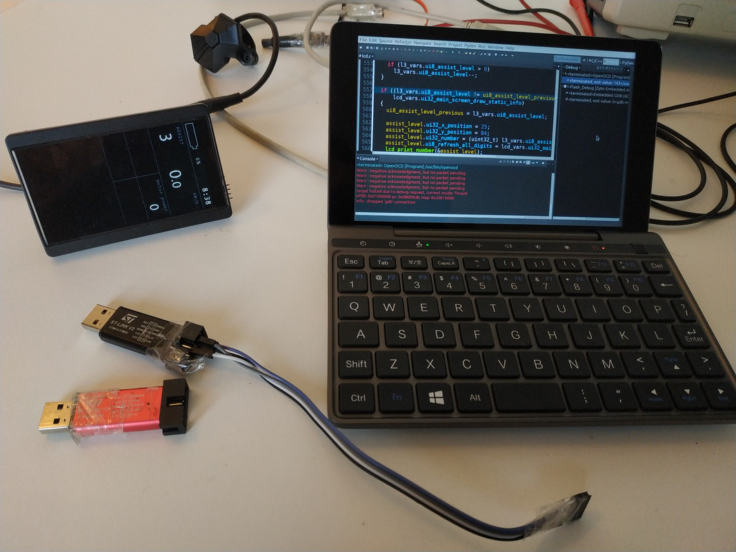
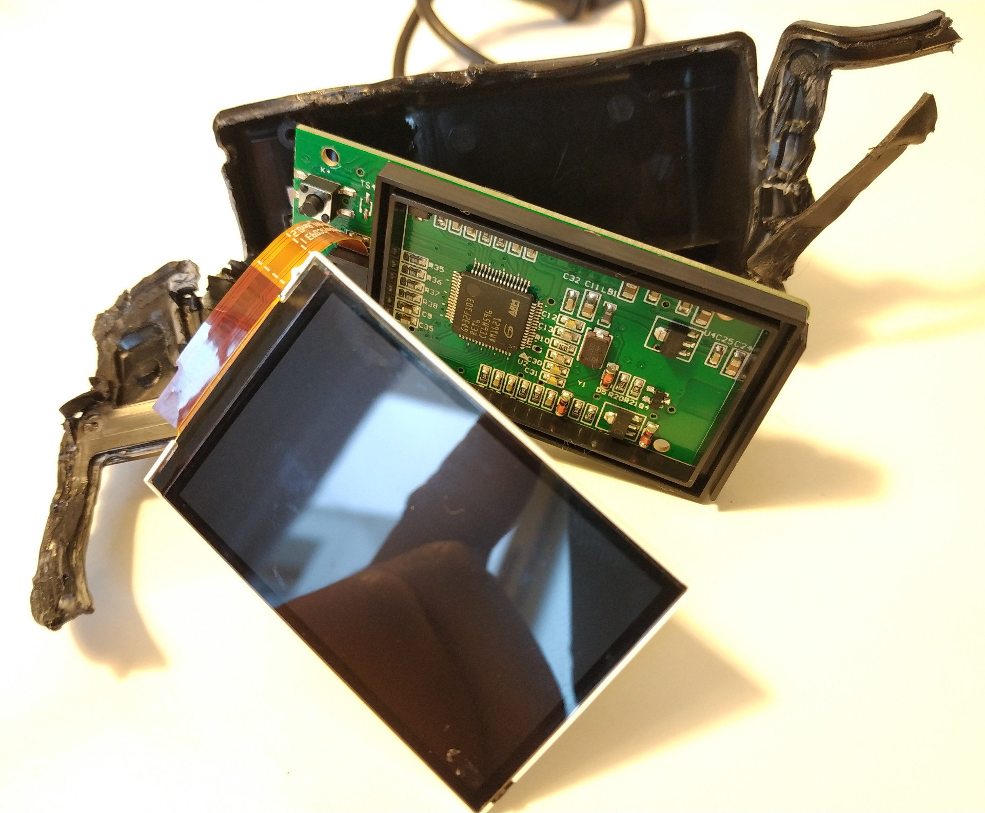
SW102 is the hardest to open and solder the flash/debug pins. It is small and has Bluetooth, something some users are asking.
Has no RTC, so no time clock.
The screen is very small but for configurations and advanced data, we can develop a mobile app.
Has the potential to communicate with the Smart Bluetooth BMS and this way integrate on the same system the EBike motor, BMS, LCD and mobile app.
The drive of LCD is not yet working.
Has 256KBytes of flash memory but about half of that is used by the Bluetooth stack. If we want to add the Bluetooth bootloader, I am afraid we can end up like LCD3, without memory.

500C, it is impossible to open to solder the flash/debug pins (unless users cut the enclosure at a specific location to access the board).
Has a medium size and share the hardware with 850C although misses the RTC (time clock).
---

I think 850C and SW102 are good ones because they are very different and may be useful for different type of users. The 500C is in the middle on this 2 and so I would skip this one.
 
casainho said:
thineight said:
casainho said:
I have the new version that seems to work very well for me, on solving the motor backwards resistance and the BOOST bug. I want to share it but I now hit the issue on SDCC that refuses to build the LCD3 firmware... so I can't share the he files..... :-(

Hope you can sort this out!
Got it, after installing SDCC 3.8.0 SVN revision #10557.

Here is the new version: https://github.com/OpenSource-EBike-firmware/TSDZ2-Smart-EBike/releases/tag/v0.19.0-beta2

Hi Casainho, i have read the commit but i don't understand where you do you solved the boost bug, can you explain me ?
 
NIPSEN said:
Hi Casainho, i have read the commit but i don't understand where you do you solved the boost bug, can you explain me ?
I think there was cases on the state machine were it would start when it should not. I change the code in the hope now everything works.
 
We really need to know the controller in use or this will be a torture :wink:
As far as I can see this is a 64x128 resolution and SPI interface?
So maybe something like this?
http://www.customlcddisplay.com/oled/monochrome-oled/64x128-oled-display-0-96-inch-oled-display.html
SH1107 Controller seems to be quite prominent on these.
casainho, can you see any markings in the display? Can you do some more pictures of hte display and back side?

casainho said:
I just shared "Files recorded with DSLogic logic analyzer, on the LCD data signals. Install DSLogic software and open the files to see the init sequence and regular data/pixels write to LCD: https://github.com/OpenSource-EBike-firmware/Color_LCD/tree/master/Bafang_LCD_SW102/DSLogic_save_files_LCD_data_signals".

Please grab that files and give a look at LCD init sequence, etc. Can you guess which LCD driver is in use??

On master you have the latest code I did, that should drive the LCD but that does not happen :-(

And here https://github.com/OpenSource-EBike-firmware/SW102_LCD_Bluetooth/tree/test_bluetooth_beacon the code I did for testing the Bluetooth.

This LCD is useless if we can't drive the LCD....
 
Nick said:
We really need to know the controller in use or this will be a torture :wink:
As far as I can see this is a 64x128 resolution and SPI interface?
No markings at all, this happens on 850C, this and 500C LCD. The markings are random numbers maybe like for production quality control.

The way I did on 850C was to replicate the init commands I recorded with the logic analyzer and I recorded the same for SW102.

Although I got the sequence, I may be doing something wrong on the code... Maybe you can look at it. Look at 850C init code to compare, as it is similar idea.

By guessing I mean try to find other codes where init codes are similar.
 
Good night, thank you very much for the work done, in all versions the assistance to walk has not given me any problem is last 19 beta2, it goes crazy even in assistance 0, thanks
 
Popo15 said:
Good night, thank you very much for the work done, in all versions the assistance to walk has not given me any problem is last 19 beta2, it goes crazy even in assistance 0, thanks
Thanks for reporting. I think assistance level 0 should be used to safely keep the motor disable, even if using walk assist or throttle. This way we can make sure motor will not work and we do not need to turn off the system on that situations we prefer to quick disable the motor without disable the system and losing data like time, etc of current travel.
 
Back
Top