TSDZ2 mid drive with 860C, 850C or SW102 displays only -- Flexible OpenSource firmware (Casainho code only)

Just want to say thanks for all the feedback. Have made a couple of improvements and finished them today. Have started on The Blinking 1 bug but have no more time for today. Will resume tonight. (Have an idea.)

There are a lot of small but very nice improvements made so far. Benefiting future displays and development as well. Will update as soon as possible.
 
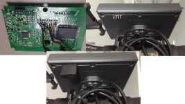
I desoldered some wires
Fv9KnRYm.jpg


from left to right j2 j3 j4 j5 j6 j7 j8.
j2 hall sensors, in the bottom the black wire (for reference)
j3, the pin in the middle is for the orange wire of the wheel speed sensor cable, the upper pin is for the brown wire of the wheel speed sensor cable
j4, the pin on the top i for the white wire of the lcd cable
j5 is for the pas sensor, red wire in the bottom (for reference)
j6 the purple wire of the wheel speed sensor calbe goes up.

I see the wiki in github. https://github.com/OpenSource-EBike-firmware/TSDZ2_wiki/wiki/How-to-install-motor-temperature-sensor and I need to know for sure if the throttle has the same wires as i think
 
elfnino said:
Francisco said:
Hello Elfnino, Thank you very much for the detailed explanation you have shared, without your help I would not have been able to understand it and get it. Now I have one last doubt, you, how did you make the connections between cables? Can you detail it to me with the same clarity as your previous message? I would appreciate it.
Well I replaced the original KT-LCD3 cable with the VLCD5 cable and just soldered it directly to KT-LCD3 mainboard.
Then I drilled two new holes on the back side of the KT-LCD3 for the sensor cables and did the connection (BREAK, GND) inside the display case where is just enough space for it.This is the elegant way with simple cabling but perhaps not the easiest.

The other options I was considering is to run extra cable from sensors directly to TSDZ2 controller and do the soldering inside.

Did you open vlcd5 to get the cable, or did you just cut the cable?

How did you connect stlink ?
 
[/quote]
Did you open vlcd5 to get the cable, or did you just cut the cable?
How did you connect stlink ?
[/quote]
just cut cable on vlcd5
you will find all the st-link connection details on the official Wiki:
https://github.com/OpenSource-EBike-firmware/TSDZ2_wiki/wiki/How-to-flash-the-Flexible-OpenSource-firmware-on-KT-LCD3
[/quote]

I'm asking you how you did it. Already familiar with options represented on wiki.
 
Hello Elfnino, I thank you very much for the information. Well, I've seen the motherboard of the kt-vcd3 and it would be very difficult to weld in there, I do not know, inside the board, what are the GND and BREAK connections (sure it's called that? BREAK). I thought that maybe I could connect the cables of the brake sensors directly on the VLCD5 cable, would it be possible? And how should I connect?
Cheers and thanks for your time.
 
Will test the latest changes today and validate that the new functions and system work as expected. If the logic is validated I will tune the parameters and make one last commit. Then submit a pull request so Casainho can review the changes and create a new beta for the community to test. Will submit the pull request tonight!
 
Francisco said:
Hello Elfnino, I thank you very much for the information. Well, I've seen the motherboard of the kt-vcd3 and it would be very difficult to weld in there, I do not know, inside the board, what are the GND and BREAK connections (sure it's called that? BREAK). I thought that maybe I could connect the cables of the brake sensors directly on the VLCD5 cable, would it be possible? And how should I connect?
Cheers and thanks for your time.

Hi Francisco,
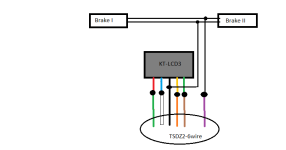
I hope this picture will explain it all.. ktlcd3-5wire + TSDZ2-6wire and break sensor (the dots represents connection)
 

Attachments

  • TSDZ-KTLCD3-6wire.png
    TSDZ-KTLCD3-6wire.png
    3 KB · Views: 1,906
hefest said:
Did you open vlcd5 to get the cable, or did you just cut the cable?
How did you connect stlink ?
just cut cable on vlcd5
you will find all the st-link connection details on the official Wiki:
https://github.com/OpenSource-EBike-firmware/TSDZ2_wiki/wiki/How-to-flash-the-Flexible-OpenSource-firmware-on-KT-LCD3
[/quote]

I'm asking you how you did it. Already familiar with options represented on wiki.
[/quote]

I have soldered the flashing pins and drilled holes on the backside of the case to ,make them available.
I glued female pins inside USB thumbdrive cover and I use it as the cover for the pins
 

Attachments

  • Bez názvu.jpg
    Bez názvu.jpg
    92.4 KB · Views: 1,902
Dear community, this is one of those great days!

First of all, pull request will be submitted very soon as promised. So look out for a GREAT beta coming your way!

Second of all:

* Slightly tuned the controller for the cruise function so it should work better for both motors.

* (I really like this one) Solved unknown bug in the UART communication making it at at least two times faster. So the external lights, walk assist and cruise function turn on and off much faster. The communication overall is operating faster!

* The UART communication has been cleaned up and is easier to change for future displays. Easier to add data for communication without changing a lot of parameters in several different places in the code.

* Overall clean up in the KT-LCD3 firmware and solved bugs. New button logic is fixed and improved a lot.

* There will be no blinking 1 error anymore. You can rest your feet on the pedals as much as you want and everything will be okay. NOTE: the same safety logic is still there but even safer! Also, the safety logic has actually even expanded to include all motor operations so it protects the motor controller, blue gear and motor in every possible use case/situation.

* New function has been created that replaces safe_tests(). The new function is called check_system. More about this in the next post.

* Firmware is also prepared for more error codes in the future as Casainho has given feedback about this.

Possible enhancement: It is possible to further develop the check_system function so it can be tuned as a blue gear protection feature. The blue gear would be more protected and hopefully less strained. A sort of software breaker/safety switch for the hardware. Nothing I have planned on doing but just throwing it out there.

In the current form, the check_system function will protect the motor and the controller from overheating and burning out if the motor gets blocked up in any way. Or maybe if the windings melt and there is a short circuit. But as the blue gear is the weakest link in the chain it is more probable that it gets stripped before anything else is damaged. So by tuning the check_system parameters it is possible to protect the blue gear more.
 
Regarding The Blinking 1 bug and the new check_system function that replaces the safe_tests function.

The problem: We want to disable the motor if the wheel or the motor gets blocked in any way. If we do not stop the motor there will basically be a short circuit in the system. The result is high amounts of current flowing through the controller and motor. This will cause a very high strain on the system.

Possible problems are stripped blue gear, burnt motor controller and maybe even overheated motor. Safety problems arise in case of an accident. Human parts may become tangled in the bike. Whatever happens it is essential that the motor is disabled if it becomes blocked in any way.

To eliminate the problem there was a function checking the torque on the pedals and the wheel speed to determine if the wheel was blocked. The result was that people were resting their feet on the pedals, for more than a set number of seconds, and the system thought the wheel was blocked as the wheel speed was not increasing. (There might have been other situations where the error code appeared also.)

The solution: We now disregard the torque on the pedals and the wheel speed. Instead, we look at the current (amps) and rotational speed (ERPS) of the motor.

Simply: if the current is higher than some threshold and the motor is not rotating faster than some threshold we will give an error code: ERROR_MOTOR_BLOCKED. This is measured for a set number of consecutive seconds and if the statement is true it will disable the motor for a set number of seconds. The error code will then be sent to the display so the user knows what has happened. After some safe time the power will resume and you can operate the mid drive as usual.

Code:
void check_system()
{
  #define MOTOR_BLOCKED_COUNTER_THRESHOLD             50    // 50  =>  5 seconds
  #define MOTOR_BLOCKED_BATTERY_CURRENT_THRESHOLD_X5  8     // 8  =>  (8 * 0.826) / 5 = 1.3216 ampere  =>  (X) units = ((X * 0.826) / 5) ampere
  #define MOTOR_BLOCKED_ERPS_THRESHOLD                10    // 10 ERPS
  #define MOTOR_BLOCKED_RESET_COUNTER_THRESHOLD       100   // 100  =>  10 seconds
  
  static uint8_t ui8_motor_blocked_counter;
  static uint8_t ui8_motor_blocked_reset_counter;

  // if the motor blocked error is enabled start resetting it
  if (ui8_system_state == ERROR_MOTOR_BLOCKED)
  {
    // increment motor blocked reset counter with 100 milliseconds
    ui8_motor_blocked_reset_counter++;
    
    // check if the counter has counted to the set threshold for reset
    if (ui8_motor_blocked_reset_counter > MOTOR_BLOCKED_RESET_COUNTER_THRESHOLD)
    {
      // reset motor blocked error code
      ui8_system_state = NO_ERROR;
      
      // reset the counter that clears the motor blocked error
      ui8_motor_blocked_reset_counter = 0;
    }
  }
  else
  {
    // if battery current (x5) is over the current threshold (x5) and the motor ERPS is below threshold start setting motor blocked error code
    if ((motor_get_adc_battery_current_filtered_10b() > MOTOR_BLOCKED_BATTERY_CURRENT_THRESHOLD_X5) && (ui16_motor_get_motor_speed_erps() < MOTOR_BLOCKED_ERPS_THRESHOLD))
    {
      // increment motor blocked counter with 100 milliseconds
      ui8_motor_blocked_counter++;
      
      // check if motor is blocked for more than some safe threshold
      if (ui8_motor_blocked_counter > MOTOR_BLOCKED_COUNTER_THRESHOLD)
      {
        // set motor blocked error code
        ui8_system_state = ERROR_MOTOR_BLOCKED;
        
        // reset motor blocked counter as the error code is set
        ui8_motor_blocked_counter = 0;
      }
    }
    else
    {
      // current is below the threshold and/or motor ERPS is above the threshold so reset the counter
      ui8_motor_blocked_counter = 0;
    }
  }
}
 
elfnino said:
hefest said:
Did you open vlcd5 to get the cable, or did you just cut the cable?
How did you connect stlink ?
just cut cable on vlcd5
you will find all the st-link connection details on the official Wiki:
https://github.com/OpenSource-EBike-firmware/TSDZ2_wiki/wiki/How-to-flash-the-Flexible-OpenSource-firmware-on-KT-LCD3

I'm asking you how you did it. Already familiar with options represented on wiki.
[/quote]

I have soldered the flashing pins and drilled holes on the backside of the case to ,make them available.
I glued female pins inside USB thumbdrive cover and I use it as the cover for the pins
[/quote]

Thanks for the images and explanation, it helps with ideas how to make it as clean looking and accessible as possible.

But I was rather asking how did you connect st-link and tsdz2, not stlink and lcd3. Wanted to see if there is an easy way of doing it without spending $20 on the speed sensor just to get the connector.

Anyway, I ordered everything that will be needed, including the speed sensor.
 
Have tested the soon to be released beta and everything seems to work great! Have submitted the pull request and I think Casainho will review the changes and create a new beta soon.

* The new check_system function can be further tuned to make it even more safe. The important thing is to have the foundation valid and this is something I have tested and verified it works. Just change parameter values and it will operate accordingly. But It should work really good as is for all users. With no problems while users are resting their feet on the pedals.

* Have tuned the controller for the Cruise function and am not entirely satisfied but would love to hear feedback from users. Should be better. Walking a fine line between different motors and different values. Future enhancement is to have Cruise user configurable from display. Anyway, feedback appreciated as always!

* Have updated the wiki with the changes and also added an Error Code table. Note that the battery menus are merged. Please familiarize yourself before configuring anything.
https://github.com/OpenSource-EBike...eatures-and-configurations-for-version-0.19.X

Will be out of town during the two coming days so this was perfect timing. Hope you like the changes and improvements!
 
casainho said:
buba said:
Still power on assistance 0 #86
--------------------------------
Will also test this today and try to reproduce it.
That one is solved as far I remember. I had to add an else to force the value to 0 when user change assist level when pedaling.

I'd like to help with the project and I have few suggestion to improve the build and release process.

We can make the whole process of releasing automatic by using CI build server to build the hex files and attach it to release assets.
 
hefest said:
elfnino said:
hefest said:
Did you open vlcd5 to get the cable, or did you just cut the cable?
How did you connect stlink ?
just cut cable on vlcd5
you will find all the st-link connection details on the official Wiki:
https://github.com/OpenSource-EBike-firmware/TSDZ2_wiki/wiki/How-to-flash-the-Flexible-OpenSource-firmware-on-KT-LCD3

I'm asking you how you did it. Already familiar with options represented on wiki.

I have soldered the flashing pins and drilled holes on the backside of the case to ,make them available.
I glued female pins inside USB thumbdrive cover and I use it as the cover for the pins
[/quote]

Thanks for the images and explanation, it helps with ideas how to make it as clean looking and accessible as possible.

But I was rather asking how did you connect st-link and tsdz2, not stlink and lcd3. Wanted to see if there is an easy way of doing it without spending $20 on the speed sensor just to get the connector.

Anyway, I ordered everything that will be needed, including the speed sensor.
[/quote]

I don't think there is any better option to flash TSDZ2 than just use the speed senzor connector..
It is althought the simplest solution..
Actually just recently I also used the spare sensor as the original stopped to work after the cable was pulled too much while tithtening it with the plastic stripes..
 
Could someone clarify whether the battery voltage readings ( e.g. for SOC or Power limit calculation) are done at LCD3 or at the TSDZ2 controller ?

I am thinking to do conversion of one of my 48V lcd3 to support also 52V just by adding and extra 200 ohm resistor. This will decrease overall voltage at lcd3 roughly by 4.4V so I am just curios whether it might impact negatively the motor control
 
elfnino said:
Francisco said:
Hello Elfnino, I thank you very much for the information. Well, I've seen the motherboard of the kt-vcd3 and it would be very difficult to weld in there, I do not know, inside the board, what are the GND and BREAK connections (sure it's called that? BREAK). I thought that maybe I could connect the cables of the brake sensors directly on the VLCD5 cable, would it be possible? And how should I connect?
Cheers and thanks for your time.

Hi Francisco,
I hope this picture will explain it all.. ktlcd3-5wire + TSDZ2-6wire and break sensor (the dots represents connection)
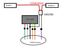
Let me add my configuration for magnetic brake sensors, for whom it may be interested.
I used this Y-splitter for the brakes, so I can disconnect-reconnect the sensor if needed, needs to solder only 2 cables.
https://www.aliexpress.com/item/32857526306.html

The schematic here below, i borrowed the image from Elfnino, did not check the colors matching as i do not have here my notes, I trust they are correct :wink:
splitter.png

Ciao
 
Have submitted another pull request so there will be an even better beta coming. Minor changes throughout.

Casainho approved the previous pull request today and I was working on the next pull request so I asked to add this in the coming beta. This means that the 0.19.0 beta 7 will likely come tomorrow or shortly thereafter.
 
elfnino said:
hefest said:
elfnino said:
hefest said:
Did you open vlcd5 to get the cable, or did you just cut the cable?
How did you connect stlink ?
just cut cable on vlcd5
you will find all the st-link connection details on the official Wiki:
https://github.com/OpenSource-EBike-firmware/TSDZ2_wiki/wiki/How-to-flash-the-Flexible-OpenSource-firmware-on-KT-LCD3

I'm asking you how you did it. Already familiar with options represented on wiki.

I have soldered the flashing pins and drilled holes on the backside of the case to ,make them available.
I glued female pins inside USB thumbdrive cover and I use it as the cover for the pins

Thanks for the images and explanation, it helps with ideas how to make it as clean looking and accessible as possible.

But I was rather asking how did you connect st-link and tsdz2, not stlink and lcd3. Wanted to see if there is an easy way of doing it without spending $20 on the speed sensor just to get the connector.

Anyway, I ordered everything that will be needed, including the speed sensor.
[/quote]

I don't think there is any better option to flash TSDZ2 than just use the speed senzor connector..
It is althought the simplest solution..
Actually just recently I also used the spare sensor as the original stopped to work after the cable was pulled too much while tithtening it with the plastic stripes..
[/quote]

This should work, I'll try it today:

https://endless-sphere.com/forums/viewtopic.php?f=30&t=93818&p=1436645&hilit=cable#p1436645
 
btslo said:
This should work, I'll try it today:

https://endless-sphere.com/forums/viewtopic.php?f=30&t=93818&p=1436645&hilit=cable#p1436645
It definitely works.. I used it since the beginning for the motor.
 
The latest beta version with the changes done by Buba:

DO NOT USE THIS BETA VERSION, USE INSTEAD LATEST NON BETA VERSION.

This version is only for developers/testers.

https://github.com/OpenSource-EBike-firmware/TSDZ2-Smart-EBike/releases/tag/v0.19.0-beta7
 
Back
Top