
48V.casainho said:@jur, are that values for 48v or 36v motor?
I have assumed that the motor is Y.
48V.casainho said:@jur, are that values for 48v or 36v motor?
Oh, my motor for development is 36V...jur said:48V.casainho said:@jur, are that values for 48v or 36v motor?
I have assumed that the motor is Y.
Let's make some assumptions and deductions to get you going:casainho said:Oh, my motor for development is 36V...jur said:48V.casainho said:@jur, are that values for 48v or 36v motor?
I have assumed that the motor is Y.
Great!!jur said:Let's make some assumptions and deductions to get you going:casainho said:Oh, my motor for development is 36V...
1. From my job I know that lower voltage electromagnetic components have fewer turns per winding. The number of turns is directly proportional to applied voltage. So, the ratio of turns between 36V and 48V is 36/48 = 3/4.
2. Inductance is proportional to the square of number of turns, so the ratio of inductance is therefore 3*3/4/4=9/16.
3. Assume the 36V motor follows these rules. therefore, its inductance is
L = 135u * 9/16 = 76u.
4. Resistance is directly proportional to number of turns, so the 36V motor resistance is
R = 0.125 * 3/4 = 0.094 ohm
Use these deduced values for development. The worst that can happen, is the optimum phase will be out by some amount. Between the 2 of us testing, we can tweak that experimentally to hone in on the correct value for L. I will give you guidance on how to tackle this.
/*
* TongSheng TSDZ2 motor controller firmware/
*
* Copyright (C) Casainho, 2018.
*
* Released under the GPL License, Version 3
*/
#ifndef CONFIG_H_
#define CONFIG_H_
// This file is the firmware configuration for the TSDZ2 motor controller,
// to run the 2 different available motors of 36V or 48V motor,
// and from 24V battery (7S) up to 52V battery pack (14S).
// *************************************************************************** //
// THROTTLE
//
// choose between following modes. You can choose for instance TORQUE_SENSOR_AND_THROTTLE and if you have
// throttle connected, the output signal used to control the motor will be the max value of both torque sensor or throttle
#define EBIKE_THROTTLE_TYPE EBIKE_THROTTLE_TYPE_TORQUE_SENSOR_AND_THROTTLE
//#define EBIKE_THROTTLE_TYPE EBIKE_THROTTLE_TYPE_PAS_AND_THROTTLE
//#define EBIKE_THROTTLE_TYPE EBIKE_THROTTLE_TYPE_THROTTLE_ONLY
// next, choose one of the both (only apply to throttle and/or PAS)
//#define EBIKE_THROTTLE_TYPE_THROTTLE_PAS_PWM_DUTY_CYCLE // direct PWM duty_cycle control, important for developers
#define EBIKE_THROTTLE_TYPE_THROTTLE_PAS_CURRENT_SPEED // control using motor current/torque and/or wheel speed
// next, if enabled, output of torque sensor algorithm is the human power (torque * cadence) other way will be the same as the torque signal
// (only apply to torque sensor)
#define EBIKE_THROTTLE_TYPE_TORQUE_SENSOR_HUMAN_POWER
// PAS configurations
// MAX cadence, where the output value of PAS processiing will be the max value
#define PAS_MAX_CADENCE_RPM 90
// *************************************************************************** //
// *************************************************************************** //
// LCD
// the firmware supports the original LCD and the more complete Kunteng LCD3 and LCD5
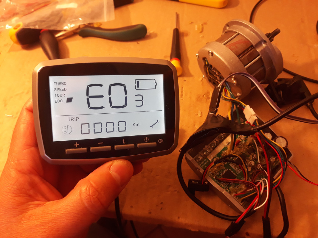
#define LCD_TYPE LCD_TYPE_TSDZ2
#define LCD_TYPE LCD_TYPE_KUNTENG // shows battery voltage, motor real time usage power, etc
// you can tune LCD assist level
#define ASSIST_LEVEL_0 0.00
#define ASSIST_LEVEL_1 0.44
#define ASSIST_LEVEL_2 0.66
#define ASSIST_LEVEL_3 1.00
#define ASSIST_LEVEL_4 1.5
#define ASSIST_LEVEL_5 2.25
// *************************************************************************** //
// *************************************************************************** //
// BATTERY
// Choose your battery pack voltage
// the cells number can be a custom value from 7S up to 14S, choose the value of your battery pack
#define BATTERY_LI_ION_CELLS_NUMBER 7 // 7S = 24V battery pack
//#define BATTERY_LI_ION_CELLS_NUMBER 10 // 10S = 36V battery pack
//#define BATTERY_LI_ION_CELLS_NUMBER 13 // 13S = 48V battery pack
//#define BATTERY_LI_ION_CELLS_NUMBER 14 // 14S = 52V battery pack
// This is the current that motor will draw from the battery
// Higher value will give higher torque and the limit of the controller is 16 amps
#define ADC_BATTERY_CURRENT_MAX 224 // (14 ADC bits step per 1 amp) so, 224 for 16 amps
// Considering the follow voltage values for each li-ion battery cell
// State of charge | voltage
#define LI_ION_CELL_VOLTS_100 4.06 // this value is used to help finding the battery SOC
#define LI_ION_CELL_VOLTS_80 3.93 // this value is used to help finding the battery SOC
#define LI_ION_CELL_VOLTS_60 3.78 // this value is used to help finding the battery SOC
#define LI_ION_CELL_VOLTS_40 3.60 // this value is used to help finding the battery SOC
#define LI_ION_CELL_VOLTS_20 3.38 // this value is used to help finding the battery SOC
#define LI_ION_CELL_VOLTS_10 3.25 // this value is used to help finding the battery SOC
#define LI_ION_CELL_VOLTS_0 3.00 // this value is used to help finding the battery SOC and is the minimum value after which the firmware don't ask more current to battery, to run the motor
// *************************************************************************** //
// *************************************************************************** //
// MOTOR CONTROLLER
// Choose PWM ramp up/down step (higher value will make the motor acceleration slower)
//
// For a 24V battery, 25 for ramp up seems ok. For an higher voltage battery, this values should be higher
#define PWM_DUTY_CYCLE_RAMP_UP_INVERSE_STEP 25
#define PWM_DUTY_CYCLE_RAMP_DOWN_INVERSE_STEP 10
// *************************************************************************** //
// *************************************************************************** //
// MOTOR
// Choose some parameters for your motor (if you don't know, just keep the following original values because they should work ok)
//
// This value should be near 0.
// You can try to tune with the whell on the air, full throttle and look at batttery current: adjust for lower battery current
#define MOTOR_ROTOR_OFFSET_ANGLE 0
// This value is ERPS speed after which a transition happens from sinewave no interpolation to have
// interpolation 60 degrees and must be found experimentally but a value of 25 may be good
#define MOTOR_ROTOR_ERPS_START_INTERPOLATION_60_DEGREES 25
// *************************************************************************** //
#endif /* CONFIG_H_ */

That's not true these days, there's services like https://macrofab.com/ and most of the chinese PCB suppliers now offer small run assembly options. You probably can't get them as cheap as the chinese ebike controllers if you use proper parts but sub $100 motor controllers should not be difficult to produce.casainho said:No, STM8 can't handle "traditional" FOC.fantasy2 said:On another thread I read that there were some doubts if this 8 bitter could implement a good and fast FOC. I haven't looked at the electronics but I'm wondering if it would be interesting to redesign the controller so it has a bit more juice. Like STM32F1/2/4. It allows for more heavy and faster calculations.
This project is not about design a controller but instead develop the firmware (the best, hopefully) for original motor controller. I was on another projects before were I dreamed with the idea of replacing the controller and found almost no one will want to mess with prototyping hardware and hardware is also a lot expensive to develop -- firmware/software on the other side is cheap and more people can join the project and develop, because the tools for development are cheap, unlike developing hardware.
lizardmech said:That's not true these days, there's services like https://macrofab.com/ and most of the chinese PCB suppliers now offer small run assembly options. You probably can't get them as cheap as the chinese ebike controllers if you use proper parts but sub $100 motor controllers should not be difficult to produce.casainho said:No, STM8 can't handle "traditional" FOC.fantasy2 said:On another thread I read that there were some doubts if this 8 bitter could implement a good and fast FOC. I haven't looked at the electronics but I'm wondering if it would be interesting to redesign the controller so it has a bit more juice. Like STM32F1/2/4. It allows for more heavy and faster calculations.
This project is not about design a controller but instead develop the firmware (the best, hopefully) for original motor controller. I was on another projects before were I dreamed with the idea of replacing the controller and found almost no one will want to mess with prototyping hardware and hardware is also a lot expensive to develop -- firmware/software on the other side is cheap and more people can join the project and develop, because the tools for development are cheap, unlike developing hardware.
We already got that feedback from TSDZ2 users, no one want touch on the motor internals and for instance, use an external controller like the KT that we already have our firmware working.fantasy2 said:It's quite a bit of work and more cumbersome to remove the old board and replace it with a new one. Most users aren't interested in that. They prefer just flashing new firmware.lizardmech said:That's not true these days, there's services like https://macrofab.com/ and most of the chinese PCB suppliers now offer small run assembly options. You probably can't get them as cheap as the chinese ebike controllers if you use proper parts but sub $100 motor controllers should not be difficult to produce.
Regarding the size of the code:
As said before, floats are expensive and slow and have rounding errors. Did you set code optimisation levels for speed or size?
casainho said:Fantasy2, you seem to be experienced, when do you join the firmware development?
casainho said:We already got that feedback from TSDZ2 users, no one want touch on the motor internals and for instance, use an external controller like the KT that we already have our firmware working.fantasy2 said:It's quite a bit of work and more cumbersome to remove the old board and replace it with a new one. Most users aren't interested in that. They prefer just flashing new firmware.lizardmech said:That's not true these days, there's services like https://macrofab.com/ and most of the chinese PCB suppliers now offer small run assembly options. You probably can't get them as cheap as the chinese ebike controllers if you use proper parts but sub $100 motor controllers should not be difficult to produce.
Regarding the size of the code:
As said before, floats are expensive and slow and have rounding errors. Did you set code optimisation levels for speed or size?
Luckily, TSDZ2 can be programmed easily from the outside, just connecting some wire pins. On KT controllers, users need to open the controller and solder wires to the board... but at least board is much more accessible than on TSDZ2.
As for code size, I am using recently SDCC 3.7.0 and I saw after a big improvement of 40% code reduction!! But I went to enable the flags for size optimization and got the same, so probably the flag is already enable by default.
Fantasy2, you seem to be experienced, when do you join the firmware development?
casainho said:An increase of 4.5mph/7.2km/h with motor heavily load is a BIG gain!!geofft said:casainho said:Also, I tested with FOC disabled, with motor current of 3.5 A and found almost no difference in the results: almost the same battery current and speed - I guess a difference may be seen at higher currents, maybe I will try again with 10A using my battery instead of the lab power supply.
FOC definitely makes a difference. I found (on training roller, wheel heavily loaded) with FOC disabled full throttle could only achieve 14mph, with FOC re-enabled this rose to 18.5mph with the motor sounding much more lively.
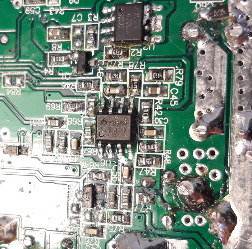
* PB5 (ADC_AIN5) | in | battery_current (14 ADC bits step per 1 amp; this signal amplified by the opamp 358)
* The battery_current is measured using the LM385 opamp in an non inverting configuration. The pin 1 is the output and has a low pass filter.
* The pin 3 (+) has the signal input and pin 2 (-) has the feedback loop, composed of R1 = 11k and R2 = 1k.
* The gain is: (R1 / R2) + 1 = (11k / 1k) + 1 = 12.
* We know that 1 Amp of battery current is equal to 14 ADC 8 bits steps, so 1 Amp = (5V / 255) * 14 = 0.275V.
* Each 1 Amp at the shunt is then 0.275V / 12 = 0.023V. This also means shunt should has 0.023 ohms resistance.
* Since there is a transistor that has a base resistor connected throught a 1K resisitor to the shunt voltage, and also the base has
* another connected resistor of 27K, I think the transistor will switch on at arround 0.5V on the shunt voltage and that means arround 22 amps.
* The microcontroller should read the turned on transistor signal on PD0, to detect the battery_over_current of 22 amps.
* PD4 | out | enable/disable 5V output of the circuit, meaning it can turn off all the system including the microcontroller itself
About the Sin-1, seems the input limits are -1 up to 1. Let's say I have a IwL = 8.5 and a Vphase = 4.8, 8.5 / 4.8 = 1.77... how can I calc the Sin-1??jur said:That would be great. I am working on getting a simulation running on my PC based on Colter's work. It's slow going because of other commitments.
You are right, the value must lie between -1 and 1. According to the pic I analyzed,casainho said:About the Sin-1, seems the input limits are -1 up to 1. Let's say I have a IwL = 8.5 and a Vphase = 4.8, 8.5 / 4.8 = 1.77... how can I calc the Sin-1??jur said:That would be great. I am working on getting a simulation running on my PC based on Colter's work. It's slow going because of other commitments.
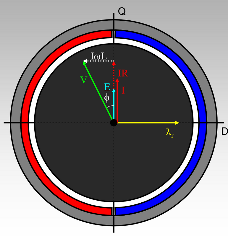
Ok, I understand now. I am slowly returning to this project. I will start to run the motor with fixed 0 angle and printing out the various operations to validate that the values do increase when I increase motor speed and/or current.jur said:You are right, the value must lie between -1 and 1. According to the pic I analyzed,casainho said:About the Sin-1, seems the input limits are -1 up to 1. Let's say I have a IwL = 8.5 and a Vphase = 4.8, 8.5 / 4.8 = 1.77... how can I calc the Sin-1??jur said:That would be great. I am working on getting a simulation running on my PC based on Colter's work. It's slow going because of other commitments.,
V must be bigger than IwL.
Even for pic 1 just before it, same holds.
Actually, while cycling to work this morning I realised something important: We don't have the I to plug into IwL! That is actually an unknown quantity. The only thing we have is filtered average battery current.casainho said:Ok, I understand now. I am slowly returning to this project. I will start to run the motor with fixed 0 angle and printing out the various operations to validate that the values do increase when I increase motor speed and/or current.jur said:You are right, the value must lie between -1 and 1. According to the pic I analyzed,casainho said:About the Sin-1, seems the input limits are -1 up to 1. Let's say I have a IwL = 8.5 and a Vphase = 4.8, 8.5 / 4.8 = 1.77... how can I calc the Sin-1??jur said:That would be great. I am working on getting a simulation running on my PC based on Colter's work. It's slow going because of other commitments.,
V must be bigger than IwL.
Even for pic 1 just before it, same holds.
I is the motor phase current. Yes, we have only the battery current mesured on the shunt because the signal is low pass filteed on hardware.jur said:Actually, while cycling to work this morning I realised something important: We don't have the I to plug into IwL! That is actually an unknown quantity. The only thing we have is filtered average battery current.
So back to analysis for me...
