
redwater said:One more thing, on boot screen is example 50,7V , but on main screen is 51,3V (0,6V above). On multimeter is 50,7V.
Best regards, and happy new year 2020 !!!
Yes, the volt display is incorrect
Mfg Michael
redwater said:One more thing, on boot screen is example 50,7V , but on main screen is 51,3V (0,6V above). On multimeter is 50,7V.
Best regards, and happy new year 2020 !!!
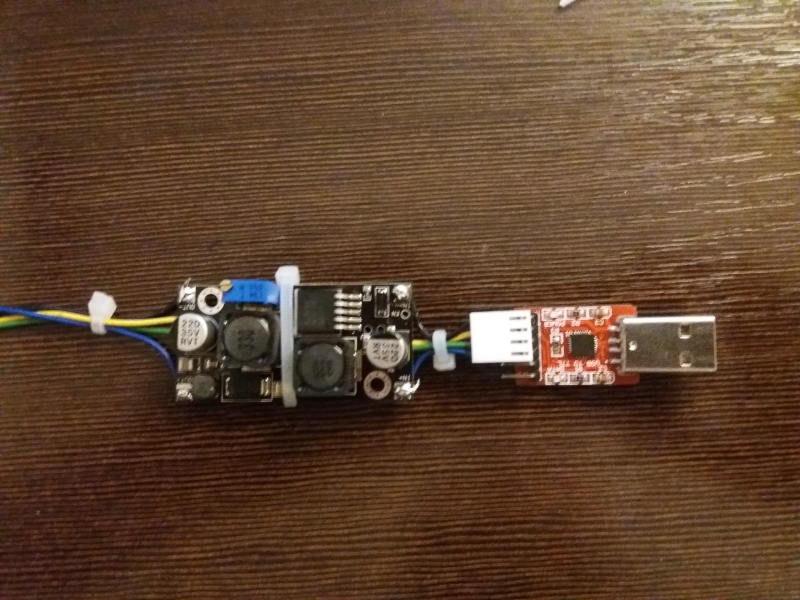
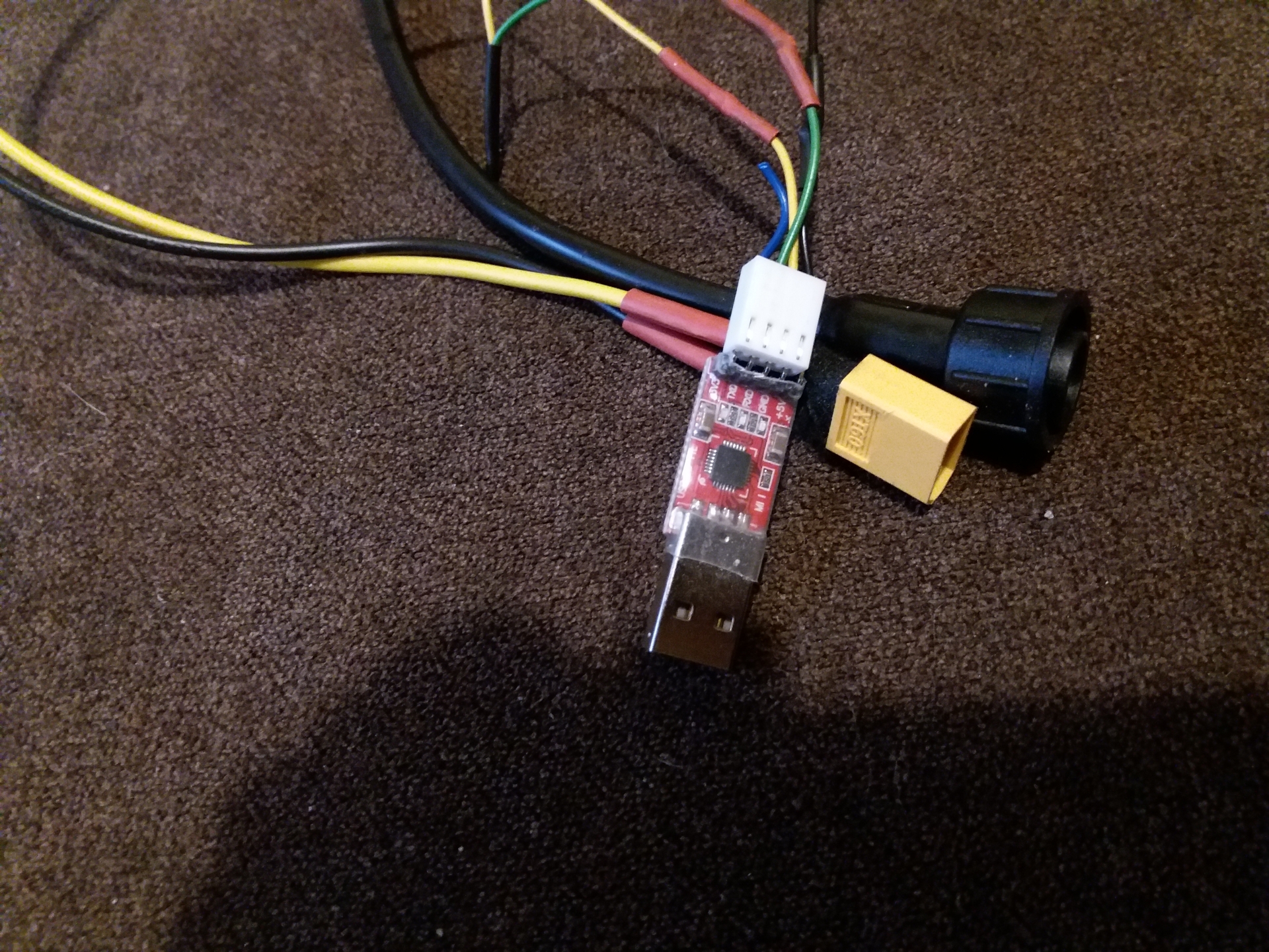
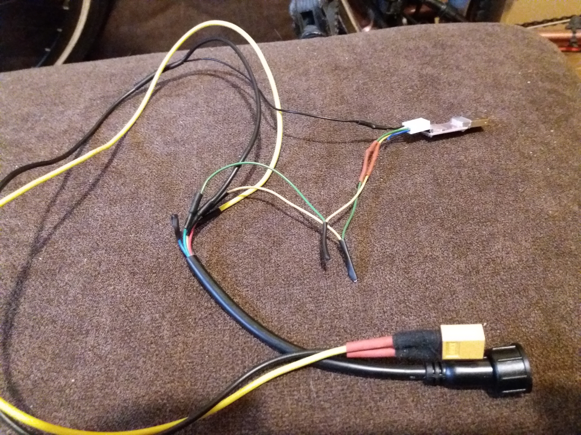
I tried that method today, and the pictures are a bit misleading. The USB adapter has those red lines on it which made me think what they meant. Then i saw that it was a c&p form the vendor site, and there is no need to mod the adapterelfnino said:No problem this is my final well working set up using "step up buck" instead of ebike buttery as power source..
The colors should match with bafang display cable
bafang extension cable - I recommend male to male (one end for bootloader box other for connecting display with TSDZ2)
https://www.aliexpress.com/item/32861639327.html
USBtoUART adapter - recomend this type as other was sensitive to AC power supply of laptop
https://www.aliexpress.com/item/32288431622.html
Step Up buck - DC booster
https://www.aliexpress.com/item/32807600304.html
")
izeman said:I tried that method today, and the pictures are a bit misleading. The USB adapter has those red lines on it which made me think what they meant. Then i saw that it was a c&p form the vendor site, and there is no need to mod the adapterelfnino said:No problem this is my final well working set up using "step up buck" instead of ebike buttery as power source..
The colors should match with bafang display cable
bafang extension cable - I recommend male to male (one end for bootloader box other for connecting display with TSDZ2)
https://www.aliexpress.com/item/32861639327.html
USBtoUART adapter - recomend this type as other was sensitive to AC power supply of laptop
https://www.aliexpress.com/item/32288431622.html
Step Up buck - DC booster
https://www.aliexpress.com/item/32807600304.html
I tried two different adapters to power the dc/dc boost converter and none of them was able to power it. The 5V line fluctuates and the converter won't ouput a stable voltage.
Am i correct in thinking that that's how it's supposed to work? The TTL adapter is meant to power the boost converter? If that's the case it ain't work here
If so, can you guys please share pictures and more details? I would like to add to the wiki as this is highly valueable.redwater said:Try XL6019. Works excellent, or get power from battery directly.
casainho said:If so, can you guys please share pictures and more details? I would like to add to the wiki as this is highly valueable.redwater said:Try XL6019. Works excellent, or get power from battery directly.
izeman said:Thank you. I tried to build that as well, and maybe failed totally 8)
Maybe also take a look here, and contribute: https://endless-sphere.com/forums/viewtopic.php?f=2&t=97083&p=1519258#p1519258

casainho said:I prepared a google file and I am sharing it so it is easier for everyone make the graphs. You will only need to edit own measured values on the tables:
I am just interested to see the graphs from other users that use the same firmware version.famichiki said:casainho said:I prepared a google file and I am sharing it so it is easier for everyone make the graphs. You will only need to edit own measured values on the tables:
The official normal torque signal range is 50-105 when viewed using the service menu of stock firmware on a VLCD5 display. How do you think these translate to the values you are seeing?
Looking at the picture, seems you have a recent version of 850C that has the sensor light installed hence that visible small hole on center bottom as also a better LCD.diagonti said:I've double-checked my wiring in accordance with the wiki. I've tried powering from both battery and a bench power supply, and I get the same results. I've tried unplugging the battery and letting it all sit for a bit, no avail there either. I've also tried re-flashing the firmware on each. Hoping I've made a simple mistake somewhere?
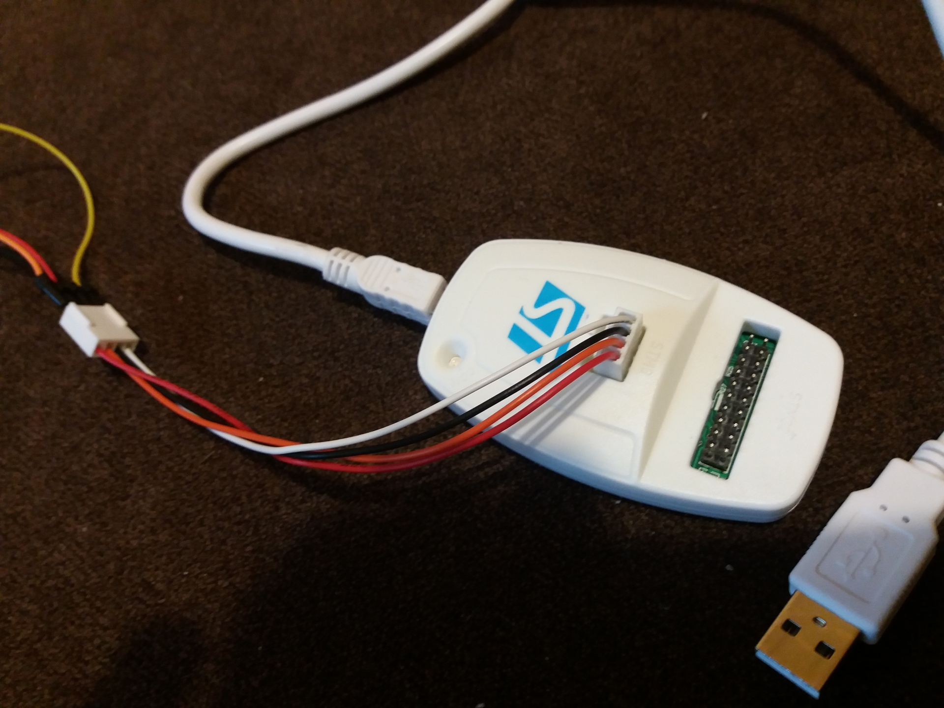
Thanks. And Vin/Orange is same voltage as Brown wire? And for programming, does it need Orange or Brown wire to be powered? It's hard to see from pictures.redwater said:VIN - orange
Rx - white <--- Tx from UART
+26-54V - brown
Tx - green <--- Rx from UART
GND - black
Colours from 850C cable ofcourse.
casainho said:Maybe your 850C hardware part the holds the voltage after power on is burned. Or maybe you are not powering correctly, check again the wires.
Did you do something that could burn the board? usually users make the mistake to use wrong connection cables or wire connections.diagonti said:casainho said:Maybe your 850C hardware part the holds the voltage after power on is burned. Or maybe you are not powering correctly, check again the wires.
Thank you for your reply. Do you know what component within that may be, so I can determine a testing procedure? I assume a transistor somewhere, hopefully user-replaceable but probably within an IC somewhere... I haven't yet cracked the casing, but that's probably the next step.
I have triple checked the wiring, torn it all down again and started from scratch, same behavior. Can you confirm the voltage I should be seeing on the orange (VIN) lead should be approximately the battery voltage, and not regulated to something lower? If they are the same, should there be any continuity between orange and brown?
Suspecting I need a new LCD, but any further insights are appreciated - I have no baseline of expected behavior for this device. If I recall correctly, this is how it functioned before flashing the firmware too, I could only get the yellow splash screen on by holding down the power button whilst running from a bench power supply, I assumed it required further negotiation to 'stay on' - can't confirm for sure now though.
Thanks again!
I guess that's a very important question which I see answered NOWHERE. I'm happy to update the WIKI with the information i gathered and with the pit falls to avoid after I have all this solved. It's way to easy to burn the display and send $50 to the junk.diagonti said:I have triple checked the wiring, torn it all down again and started from scratch, same behavior. Can you confirm the voltage I should be seeing on the orange (VIN) lead should be approximately the battery voltage, and not regulated to something lower? If they are the same, should there be any continuity between orange and brown?
casainho said:Did you do something that could burn the board? usually users make the mistake to use wrong connection cables or wire connections.
I have a few boards burned with the same symptoms and I could never repair them.
diagonti said:casainho said:Did you do something that could burn the board? usually users make the mistake to use wrong connection cables or wire connections.
I have a few boards burned with the same symptoms and I could never repair them.
Not that I am aware of - I'm usually pretty good with paranoid checking of everything prior to applying any power - but of course, anything is possible. If you've seen the same symptoms, I will assume I require a new display.
izeman said:What setup do you guys recommend for UPDATING both, the display and the controller?
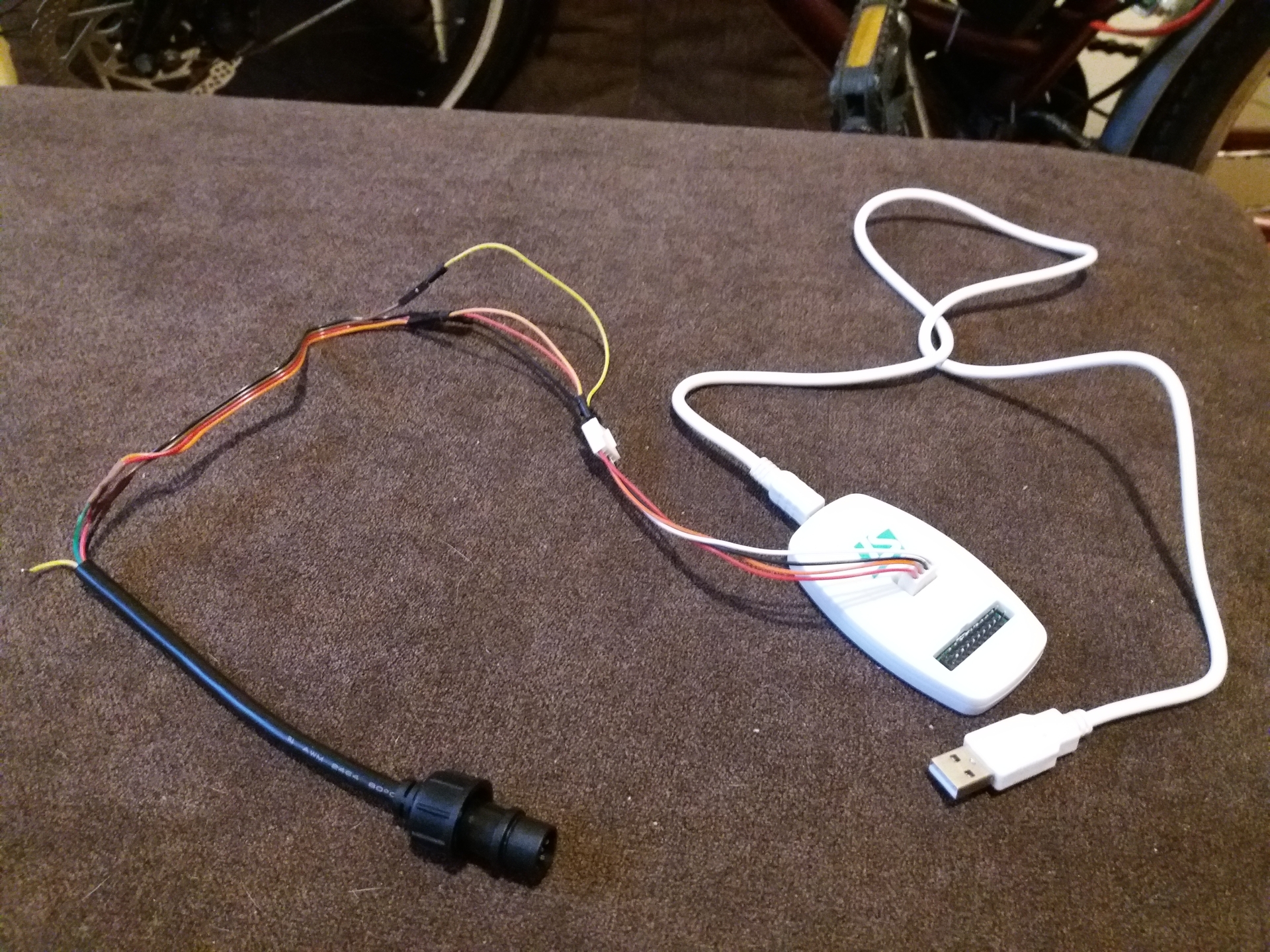
Following the WIKI, it's recommended to cut off the connector of the 850C, and hardwire it to an extension wire that fits to the TSDZ2's original plug hardness? So you need an extension wire and cut that to the correct length, so one end is soldered to the display and the other end (female connector) fit's to the TSDZ2's male connector.
And then you need a second extension wire cut in two pieces. One piece to update the display (eg via bootloader mode) and the other one to update the controller (via STLink).
So far correct? Or is there a better way?
izeman said:Thanks. And Vin/Orange is same voltage as Brown wire? And for programming, does it need Orange or Brown wire to be powered? It's hard to see from pictures.redwater said:VIN - orange
Rx - white <--- Tx from UART
+26-54V - brown
Tx - green <--- Rx from UART
GND - black
Colours from 850C cable ofcourse.
Rydon said:It is probably not the display. The display stays on the splash screen when it can't communicate with the motor controller. Check rx and tx to be sure they are not reversed. Also, check simple things like brake sensors.
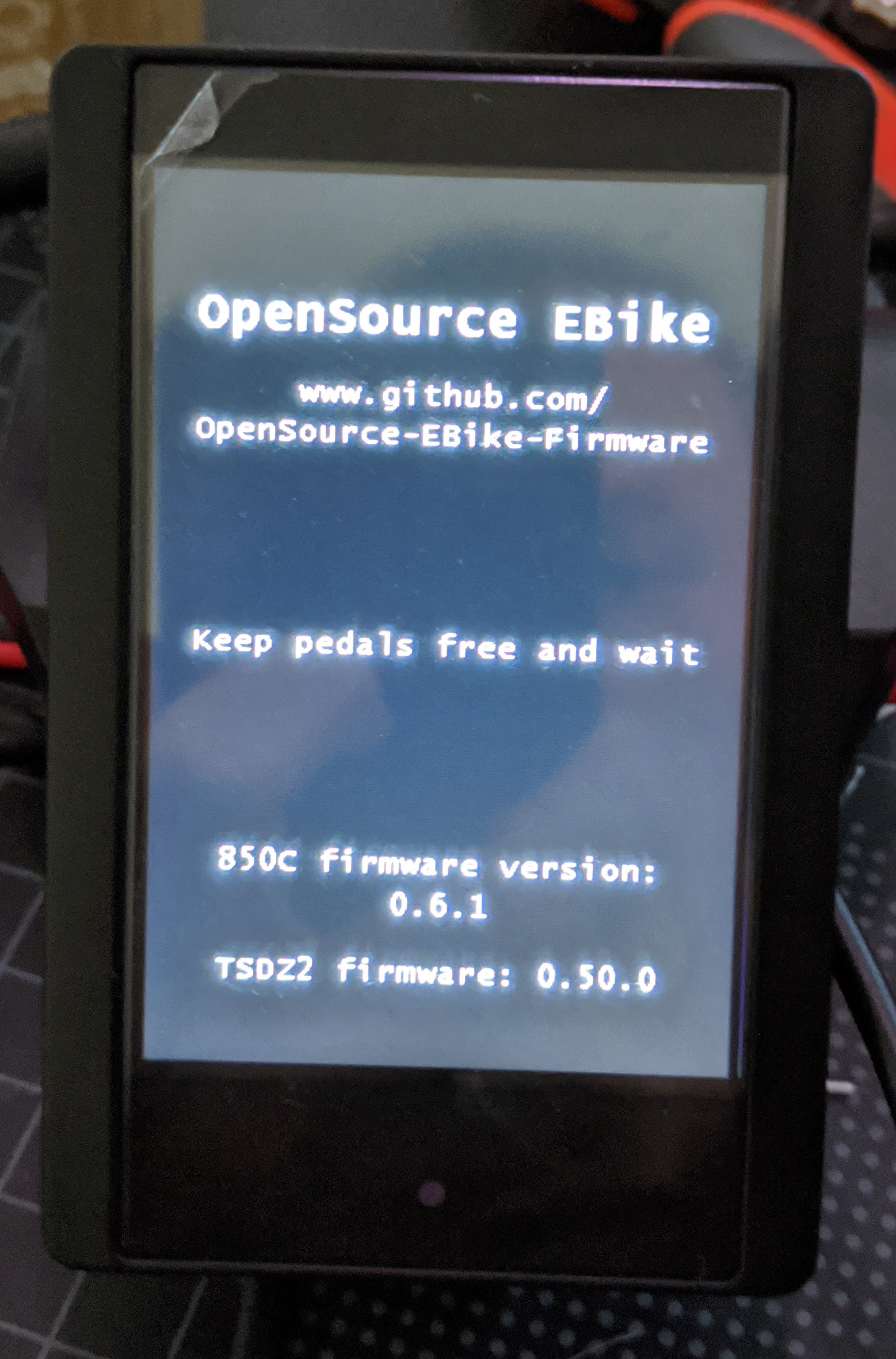
On last version of firmwares, the system is a bit more complex and yes, it reads first the firmware version from the motor controller so if it shows the version "0.50.0" that means it is communicating with the motor controller.diagonti said:Rydon said:It is probably not the display. The display stays on the splash screen when it can't communicate with the motor controller. Check rx and tx to be sure they are not reversed. Also, check simple things like brake sensors.
Thank you for your reply. The display successfully determines the firmware version of the controller - tx/rx do not appear to be switched. Brake sensors are not currently connected for simplicity - do I need to pull this to +5v or GND for the display/controller to init? Obviously the 850C does not directly connect to the brake sensors.