TSDZ2 OSF for all displays, VLCD5-VLCD6-XH18, LCD3, 860C-850C-SW102.

No, the only bike with the fixing block is the hard-tail which has the TSDZ2B 48v mid-drive, the others with the TSDZ2 36v mid-drives being full suspension have the epoxy putty wedge pieces and theTSDZ2B embossed fixing plates, could 3D print the wedge pieces but a bit of a faff as the epoxy putty just forms to the right shape. Zoom in on the first photo with the under-slung battery and you see the grey wedge piece. Yes the motor pivots to the down tube. I have used Loctite red pipe thread sealant which not a high strength thread lock to stop the nut coming loose.
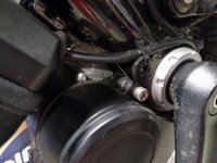
What's the purpose of the epoxy block? To prevent the motor from hammering on the down tube if the BB nut comes loose?

Last week I moved my TSDZ2 motor from my Raleigh Mtn Tour Seneca to a new/used hardtail Raleigh M80. I did not install the chain stay fixing block. It's nice to keep the kickstand. Only the BB nut received blue Loctite. I painted whiteout on the BB nut so I can see at a glance if it has loosened or not.

IMG_3839.jpeg
 
No, I put black insulation tape across the top of the mid-drive casing and the underside of the frame down-tube, the mid-drive is loose and swung away from the down-tube, I then mix the Epoxy Putty together, I use Quiksteel 16402 as it is pre-mixed. Next I form it into a larger than needed wedge shape, place it on top of the mid-drive casing, then swing the mid-drive up and against the down-tube squeezing and forming the epoxy wedge so it follows the contours of the top of the mid-drive casing and the underside of the frame down-tube, tighten the BB nut enough to hold the mid-drive in place whilst the epoxy putty hardens. Then I fully tighten everything. In my case I use around half the tube of the epoxy.
 

Attachments

  • wedge.jpg
    wedge.jpg
    4.1 MB · Views: 24
Still don't understand how the epoxy wedge acts as an anti rotation device. Anti rotation in what direction?

Wouldn't a piece of hard rubber between down tube and motor serve the same purpose?
 
.......
Zambam, In the early days I have had the TSDZ2 BB nut's come loose hence the reason for the epoxy putty, Loctite red and change to TSDZ2B embossed fixing plates. I am 90% sure that I have seen a Tongsheng comment saying that you can get away with just using the TSDZ2B embossed fixing plate only to stop the drive rotating, after all I did have a AKM mid-drive that used the Bafang BB twin nut system which I guess Tongsheng has copied on the B version embossed fixing plate.


Look at Step 4
Tip:

If the fixing block doesn't work with your frame, you can mount the motor without it. If the motor rotates over time, don't overtighten the lockring. Instead, rotate it snugly against the bottom bracket housing (in the direction of pedaling), hand tighten for now.

But I would myself still use an epoxy putty wedge, have not tried it on the high power rated mid-drives.
Didn't see your edit till now. Rotate motor in the direction of pedaling? That'd be toward the chain stay. If the lock ring loosens, wouldn't the motor rotate and slam against the down tube, possibly breaking the motor casing at the fillet?
 
If the motor comes loose it will rotate and hit the down tube that's correct, I have used the epoxy wedge as stop piece, the difference is that rather than having a point load on the motor casing which will break the casing, I have spread the load across top of the motor case and the under-side of the down-tube, I will not say the wedge is a 100% fix but so far I have not had a cracked motor casing.
Regarding the rubber block, I have used hard neoprene blocks before, I made a sandwich of 1mm, 2mm and 3mm thick pieces to get a suitable shape. Work fine on Giant Anthem frame with a TSDZ2 mid-drive, but it came loose, motor casing was fine but put a flat spot / dent in the underside of down-tube. So as before I use the contouring of the wedge to spread the rotational load and a TSDZ2B fixing plate only to stop the mid-drive rotating along with the Loctite red on the BB nut.
As you know the fixing block is fine if your have a hard-tail as it stops movement in both directions but not a lot use on a full suspension frame, I have even considering grinding the mount point for the fixing block off the casting when used on a full suspension frame.
 
Last edited:
I have a tsdz2 engine cover leaning against a sloping frame tube. I have a piece of hard rubber between the motor and the tube. The motor is fixed like this and it doesn't move and nothing has been damaged yet. Mileage over 17,000 km.
 
I have a tsdz2 engine cover leaning against a sloping frame tube. I have a piece of hard rubber between the motor and the tube. The motor is fixed like this and it doesn't move and nothing has been damaged yet. Mileage over 17,000 km.
pav, That is great, there is only winning. Have found that on some frames the wall thickness of the frame tubes is a bit on the thin side, found this when fitting threaded rivet inserts for battery mounts.
 
hi, i want to measure torque sensor output from stm8s105
do you know the pin number of torque sensor input pin number on stm8s105?
regards
 
I don’t understand the instructions for calibrating torque sensor on tsdz2 860c. Do i only need to put weight on the crank side pedal?
Correct, drive side (right hand side) is the only one you need to stand on. (or apply the 25kg weight for the conversion factor)
 
.......For the 25kg part, should I leave `Default weight` set to `no`?............ Torque sensor calibration instructions · Issue #20 · emmebrusa/TSDZ2-Smart-EBike-860C

Great instructions, easier to read than the supplied ones.

Sorry, don't know about the default weight setting, I've never set it myself.

I see you have the 860C which doesn't have full instructions provided for torque calibration. Have you read the instructions for the VLCD5 which I assume are same/similar - page 2 in below. There's a lot of detail within it.

Ok those instructions help...but I'm still confused how to set "Torque adc step", it mentions "specific instructions" but never tells you what they are...
 
Hi all, I have this problem, when compiling Java asks to confirm the firmware, but then appears an error that can not connect to the device. At the same time the STVP program works fine and I made backups.
 
Ok those instructions help...but I'm still confused how to set "Torque adc step", it mentions "specific instructions" but never tells you what they are...

ADC Step is only used if Torque sensor advanced is disabled.

Presumably you've enabled Torque sensor advanced, because you've done the calibration and have figures to enter? In which case ADC step is irrelevant to you (as I understand it, it's a simple way to calibrate). Also ADC Step applies only in Power mode.

I've based this on my understanding of the linked PDF - it is quite hard to follow so I may be wrong.
 
Ok those instructions help...but I'm still confused how to set "Torque adc step", it mentions "specific instructions" but never tells you what they are...


OK, I did understand correctly - ADC step is not needed/used if you have calibrated.

From the man himself:

mbrusa - "There is another wrong parameter, it is Torque sensor-> Torque adc step, why 120?
It is not important because it is only used in Power mode with calibration disabled."

 
Thank you, i check the tsdz2 controller board, cant find any connection to PB3 , pin 18, am i doing something wrong?
if you want to measure torque sensor output from stm8s105, it's pin 18, otherwise the connection of the torque sensor is on the only small white 2 pins plug (black wire and red wire) near the big condensator...
 

Attachments

  • STM8S105x4-6_pinout.PNG
    STM8S105x4-6_pinout.PNG
    51.5 KB · Views: 6
OK, I did understand correctly - ADC step is not needed/used if you have calibrated.

From the man himself:

mbrusa - "There is another wrong parameter, it is Torque sensor-> Torque adc step, why 120?
It is not important because it is only used in Power mode with calibration disabled."

How does this look? Turned calibration on, copied "ADC torque step calc" to "Torque adc step adv". I'll go try it out later today to see if the human power numbers are better.

IMG_0552.jpg

EDIT: I converted "Weight on pedal" from kg to lb, so from 24 to ~53, reupdated torque adc step and torque adc step adv accordingly and now I feel my human power numbers are pretty good!
 
Last edited:
After compiling, can I just grab the firmware file from the releases folder and flash that file? If I have a problem with flashing from Java
 
I'm using Hybrid mode and I'd like to increase the sensitivity, i.e. make the motor more helpful even if I don't apply too much force to the pedals. I plan to use the torque sensor calibration in OSF to do this. The TE ("Pedal torque adc offset") value found on my e-bike is 161. Is it a good idea to set the "Pedal torque adc max" to 201 only (i.e. delta 40) to increase pedal sensitivity? I don't want to use my maximum force to push the pedals while riding.
 
Back
Top