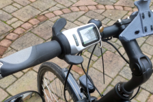
TSDZ2 OSF for all displays, VLCD5-VLCD6-XH18, LCD3, 860C-850C-SW102.

Thanks for your suggestions. I have triple checked and tested my wiring but can’t find a problem there.
With the battery & display on, I’m getting 4.3V with correct polarity between the sensor’s 5V & GND legs.
I have continuity from the centre leg of the sensor (Vout) to the throttle pin on my 8-pin connector.
With the battery & display on, I’m seeing approx 300mV between the centre and ground legs of the sensor (Ambient temp is about 30deg C) but still only a fixed 18.9 degrees on my VLCD5.
I used this Temp mod so far only on 6 pin Displays. Could it be thst within the display there is still some circuity connected to that wire (i.e. Pull-downs etc…)? Maybe try and cut that wire between Controller and Display, so that really only the sensor is connected to that input of the controller / mcu?
 
I used this Temp mod so far only on 6 pin Displays. Could it be thst within the display there is still some circuity connected to that wire (i.e. Pull-downs etc…)? Maybe try and cut that wire between Controller and Display, so that really only the sensor is connected to that input of the controller / mcu following the Temp Sensor Wiki
I used this Temp mod so far only on 6 pin Displays. Could it be thst within the display there is still some circuity connected to that wire (i.e. Pull-downs etc…)? Maybe try and cut that wire between Controller and Display, so that really only the sensor is connected to that input of the controller / mcu?
I followed the Temp Sensor Install Wiki instructions for 8 pin controllers. It says to cut the throttle wire and connect the centre leg of the sensor to that wire. I assumed the sensor is connected to the end of the wire that goes to the display (and not to the end of the wire still connected to the controller PCB.) Now I’m not so sure about that :unsure:
 
I followed the Temp Sensor Install Wiki instructions for 8 pin controllers. It says to cut the throttle wire and connect the centre leg of the sensor to that wire. I assumed the sensor is connected to the end of the wire that goes to the display (and not to the end of the wire still connected to the controller PCB.) Now I’m not so sure about that :unsure:
No, the Vout leg from the sensor definetely has to be connected with the controller - not the display. This also makes sense if you think about it: You reprogram only the controller - not the Display. So only tge controllers ‚knows‘ after reprogramming whst to do with the new input signal.
 
No, the Vout leg from the sensor definetely has to be connected with the controller - not the display. This also makes sense if you think about it: You reprogram only the controller - not the Display. So only tge controllers ‚knows‘ after reprogramming whst to do with the new input signal.
That’s where I went wrong…. Rookie mistake!
Thanks for your help @endlessolli… much appreciated 👍
 
Never heard of such a problem.
A few questions to understand:
Have you calibrated the torque sensor?
Do you have throttle installed?
No errors displayed?
Hello Mbrusa. Yes the torque sensor is calibrated. The bike is riding good and i can defenitely feel the sensor working. I have no throttle nor do i have errors. However. I had installed brake sensors. These sensors broke down both very quickly. The reed switch remained high/closed. So i took them of. The fault occurred later . So i didn't thought about it. But maybe there is some short connection in the manipulated cableharness.... Also it looks like if i have used the motor with a powerfull run for example 5 minuts at 400w. Then the push is also harder when starting up next time. It looks like it has some storaged power it needs to get loose. For some reason.
Could it be something with the option bite file?
Thanks for replying
 
I'm having trouble with the JavaConfigurator on windows 10 64-bit. I have installed latest version of the configurator, Java and ST-Links visual programmer. I have tried to turn off antivirus and firewall and tried different builds. Same setup is working well on my other PC. I get the message on below picture:
Error on compile and flash.jpg
Any help appreciated.
 
I bought a 48 watt TSDZ2 and an 860C controller in the summer of 2020, and I'm finally getting around to installing it. It's for a 52 volt road bike.

I'm hoping someone can confirm whether I have identified a suitable release for the job. I am looking at the open source firmware TSDZ2-v20.1C-860C. github page

I have read the manuals and I like what it offers. It's an older version that originates in 2021, but it appears it's continuing to receive updates.

TIA
 
I bought a 48 watt TSDZ2 and an 860C controller in the summer of 2020,....
Did you bought this as a working kit?
If so, there is a chance that OSF already is installed or the 860C display is a stock Tsdz2 display and you need the Java version of OSF.
 
No, I bought them a la carte from China.
If you bought the tsdz2 with or without display and the 860C separately, you must indeed flash the controller and the display bootloader.
 
Last edited:
Thank you.

I'm hoping someone can confirm whether I have identified a suitable release for the job. I am looking at the open source firmware TSDZ2-v20.1C-860C. github page
 
You've already been asked a question:
"Did you purchase the motor and display in one kit?"
And I add:
"Is the engine working with stock firmware and 860C display?"

If the answers are yes, you must use this OSF:
Release Open source firmware TSDZ2-v20.1C.2-update-2 VLCD5-VLCD6-XH18 · emmebrusa/TSDZ2-Smart-EBike-1
and only the motor flashes.

If not, you have to use this:
Release Open source firmware TSDZ2-v20.1C.4-860C-update-4 · emmebrusa/TSDZ2-Smart-EBike-860C
and both motor and display flash.
 
I recently bought the vlcd10 display.
I have tried it with the mbrusa firmware, but it does not work correctly.
There is no difference between levels 1 and 2 of assistance and the battery charge percentage does not work well either.
Will you be able to add support in a future version?
Thank you very much for your excellent work.
 
I don't know the VLCD10 display, but if it works with Tonsheng protocol, it should just be a settings issue.
You write that there is no difference between levels 1 and 2 of assistance, I therefore assume that there are 5 levels, if there were 4 you can customize them in the configurator.
If there are 5, levels 1 to 4 in the configurator correspond to 2 to 5 on the display. Level 1 on the display is 70% of level 2 (level 1 on the configurator), you can change this percentage value in the main.h file on the line #define ASSIST_PEDAL_LEVEL01_PERCENT.
The remaining battery percentage is independent of the type of display, if it does not match, you must check the actual capacity and change the "Battery capacity calibration" value.
While for the battery bars, you can set VLCD5 if there are 6, VLCD6 if there are 4. 5 bars are not provided, so choose the one you prefer. The voltage values corresponding to the bars can be set in the "Battery cell setting" section.
 
Last edited:
Thanks for your contribution.
I hadn't realized that there are five levels of assistance and five battery bars.
I'll see if I can fix it with the configuration values.
The question is to use vlcd5 or vlcd6 in the java configurator.
Which one would you recommend?
 
If I use the battery values for vlcd5, what values should I use 0 to 5 or 1 to 6?
Can assistance levels be changed in main.h and config.h?
Can I change battery settings for vlcd5 in main.h and config.h?
I use linux to configure the firmware and before flashing I compile the main.ihx file.

If I change the values and there are no errors in the firmware compilation, is it safe to flash?

Thanks.
 
I managed to compile the main.ihx file without errors by modifying main.h, config.h and ebike_app_c.
Basically I have added a level of assistance (I have called it "EXTRA") and I have removed a level of battery to the values of the VLCD5 display.
I'm crossing my fingers and I'll flash it tomorrow.
I assume that when compiling without errors the firmware will be valid...
 
In the main.h file you only need to change the value on the #define ASSIST_PEDAL_LEVEL01_PERCENT line.
If you don't use the configurator, you can change the values of the parameters in the config.h file, just be careful to understand their function.
I don't know what your programming knowledge is, but I advise you against modifying ebike_app.c, to obtain 5 bars I think it is possible to set it to 6 (VLCD5) and two bars with equal voltage values.
 
What value should I put in #define ASSIST_PEDAL_LEVEL01_PERCENT?
Default value is 70.
80, 90, 95?
 
This are the lines I have changed in ebike_app_c
#else // ENABLE_VLCD5 or 850C
if(ui16_battery_voltage_soc_filtered_x10 > ((uint16_t) (BATTERY_CELLS_NUMBER * LI_ION_CELL_VOLTS_7_X100 / 10))) {ui8_battery_state_of_charge = 8;} // overvoltage
else if(ui16_battery_voltage_soc_filtered_x10 > ((uint16_t) (BATTERY_CELLS_NUMBER * LI_ION_CELL_VOLTS_6_X100 / 10))) {ui8_battery_state_of_charge = 7;} // 5 bars -> SOC reset
else if(ui16_battery_voltage_soc_filtered_x10 > ((uint16_t) (BATTERY_CELLS_NUMBER * LI_ION_CELL_VOLTS_5_X100 / 10))) {ui8_battery_state_of_charge = 6;} // 5 bars -> full
else if(ui16_battery_voltage_soc_filtered_x10 > ((uint16_t) (BATTERY_CELLS_NUMBER * LI_ION_CELL_VOLTS_4_X100 / 10))) {ui8_battery_state_of_charge = 5;} // 4 bars
else if(ui16_battery_voltage_soc_filtered_x10 > ((uint16_t) (BATTERY_CELLS_NUMBER * LI_ION_CELL_VOLTS_3_X100 / 10))) {ui8_battery_state_of_charge = 4;} // 3 bars
else if(ui16_battery_voltage_soc_filtered_x10 > ((uint16_t) (BATTERY_CELLS_NUMBER * LI_ION_CELL_VOLTS_2_X100 / 10))) {ui8_battery_state_of_charge = 3;} // 2 bars
else if(ui16_battery_voltage_soc_filtered_x10 > ((uint16_t) (BATTERY_CELLS_NUMBER * LI_ION_CELL_VOLTS_1_X100 / 10))) {ui8_battery_state_of_charge = 2;} // 1 bar
else if(ui16_battery_voltage_soc_filtered_x10 > ((uint16_t) (BATTERY_CELLS_NUMBER * LI_ION_CELL_VOLTS_0_X100 / 10))) {ui8_battery_state_of_charge = 1;} // blink -> empty
else {ui8_battery_state_of_charge = 0;} // undervoltage
#endif

Lines modified in main.h
// assist pedal level mask
#define ASSIST_PEDAL_LEVEL0 0x10
#define ASSIST_PEDAL_LEVEL01 0x80
#define ASSIST_PEDAL_LEVEL1 0x40
#define ASSIST_PEDAL_LEVEL2 0x02
#define ASSIST_PEDAL_LEVEL3 0x04
#define ASSIST_PEDAL_LEVEL4 0x06
#define ASSIST_PEDAL_LEVEL5 0x08

// cell bars
#else // ENABLE_VLCD5 or 850C
#define LI_ION_CELL_VOLTS_7_X100 (uint16_t)((float)LI_ION_CELL_OVERVOLT * 100)
#define LI_ION_CELL_VOLTS_6_X100 (uint16_t)((float)LI_ION_CELL_RESET_SOC_PERCENT * 100)
#define LI_ION_CELL_VOLTS_5_X100 (uint16_t)((float)LI_ION_CELL_VOLTS_FULL * 100)
#define LI_ION_CELL_VOLTS_4_X100 (uint16_t)((float)LI_ION_CELL_VOLTS_4_OF_5 * 100)
#define LI_ION_CELL_VOLTS_3_X100 (uint16_t)((float)LI_ION_CELL_VOLTS_3_OF_5 * 100)
#define LI_ION_CELL_VOLTS_2_X100 (uint16_t)((float)LI_ION_CELL_VOLTS_2_OF_5 * 100)
#define LI_ION_CELL_VOLTS_1_X100 (uint16_t)((float)LI_ION_CELL_VOLTS_1_OF_5 * 100)
#define LI_ION_CELL_VOLTS_0_X100 (uint16_t)((float)LI_ION_CELL_VOLTS_EMPTY * 100)
#endif

// power assist level
#define POWER_ASSIST_LEVEL_OFF 0
#define POWER_ASSIST_LEVEL_ECO (uint8_t)(POWER_ASSIST_LEVEL_1 / 2)
#define POWER_ASSIST_LEVEL_TOUR (uint8_t)(POWER_ASSIST_LEVEL_2 / 2)
#define POWER_ASSIST_LEVEL_SPORT (uint8_t)(POWER_ASSIST_LEVEL_3 / 2)
#define POWER_ASSIST_LEVEL_TURBO (uint8_t)(POWER_ASSIST_LEVEL_4 / 2)
#define POWER_ASSIST_LEVEL_EXTRA (uint8_t)(POWER_ASSIST_LEVEL_5 / 2)

Lines changed in config.h
#define LI_ION_CELL_VOLTS_4_OF_5 3.85
#define LI_ION_CELL_VOLTS_3_OF_5 3.65
#define LI_ION_CELL_VOLTS_2_OF_5 3.35
#define LI_ION_CELL_VOLTS_1_OF_5 3.10

#define POWER_ASSIST_LEVEL_1 40
#define POWER_ASSIST_LEVEL_2 100
#define POWER_ASSIST_LEVEL_3 160
#define POWER_ASSIST_LEVEL_4 220
#define POWER_ASSIST_LEVEL_5 250
#define TORQUE_ASSIST_LEVEL_1 30
#define TORQUE_ASSIST_LEVEL_2 60
#define TORQUE_ASSIST_LEVEL_3 90
#define TORQUE_ASSIST_LEVEL_4 120
#define TORQUE_ASSIST_LEVEL_5 150
#define CADENCE_ASSIST_LEVEL_1 60
#define CADENCE_ASSIST_LEVEL_2 85
#define CADENCE_ASSIST_LEVEL_3 110
#define CADENCE_ASSIST_LEVEL_4 135
#define CADENCE_ASSIST_LEVEL_5 150
#define EMTB_ASSIST_LEVEL_1 2
#define EMTB_ASSIST_LEVEL_2 5
#define EMTB_ASSIST_LEVEL_3 8
#define EMTB_ASSIST_LEVEL_4 12
#define EMTB_ASSIST_LEVEL_5 15
#define WALK_ASSIST_LEVEL_1 30
#define WALK_ASSIST_LEVEL_2 35
#define WALK_ASSIST_LEVEL_3 40
#define WALK_ASSIST_LEVEL_4 45
#define WALK_ASSIST_LEVEL_5 50
 
The change you made to the levels is not good, you don't have to add another level, it is already foreseen in the code..
The fifth level, if present on the display, is between OFF and ECO (1 of 4), it is the lowest level of the 5, therefore:
#define POWER_ASSIST_LEVEL_1 60 will be level 2 on the display
#define POWER_ASSIST_LEVEL_2 120 will be level 3 on the display
#define POWER_ASSIST_LEVEL_3 200 will be level 4 on the display
#define POWER_ASSIST_LEVEL_4 300 will be level 5 on the display
This applies to all types of assistance.

ASSIST_PEDAL_LEVEL01_PERCENT 70, means that the new level (1 of 5), is 70% of level 2 of 5.
By setting it to 100%, Level 1 will be the same as Level 2.
So if you write "There is no difference between assistance levels 1 and 2", and you want to increase the difference between the two, you need to decrease the % value, try setting:
#define ASSIST_PEDAL_LEVEL01_PERCENT 50.
Do not add or change anything else to the main.h file.

In the config.h file, do not add any other definitions, just change the values.
For the voltage of the notches set these:
#define LI_ION_CELL_VOLTS_5_OF_6 3.90
#define LI_ION_CELL_VOLTS_4_OF_6 3.90
#define LI_ION_CELL_VOLTS_3_OF_6 3.70
#define LI_ION_CELL_VOLTS_2_OF_6 3.50
#define LI_ION_CELL_VOLTS_1_OF_6 3.30

Obviously the ebike_app.c file should not be modified.
 
Back
Top