• Hello ES! We could use some help to get us past the finish line on building the new knowledgebase for the forum.
    Can you donate? Please see our fundraising page. Thank you!

VESC based INNOTRACE M620 Simple motor controller

The controller can probably make more than 10kW (100V 100A). At that power the M620 motor stator will probably overheat in a minute or so while the controller will probably be around 50 C so the controller is not the bottleneck here.
 
You completed the initial version much faster than I anticipated.
Fingers crossed and waiting for the initial test results!
Btw - can the controller have a build in step down with meaningful current to support reasonable lightning without external dc-dc unit?
 
Probably can if you go back to design with two boards to have more space. The connectors for lights for this controller are occupied for different purposes though (USB, Bluetooth, CAN).
 
Last edited:
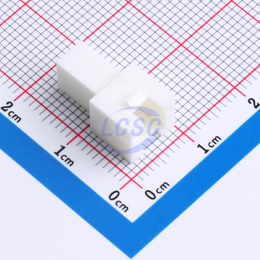
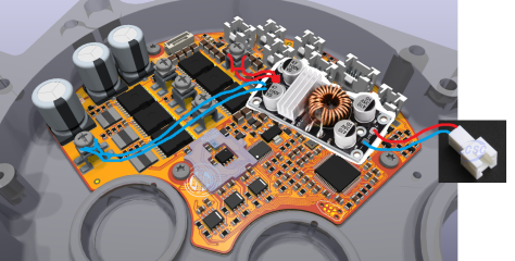
But the best solution would be just to purchase a module on AliExpress, a connector for the light cables, terminals for the connector, some ring terminals and heat shrink wrap and make a dongle and put it inside the motor.


1785470913279.png

You still need an external stuff to control the lights or at least a BMS with turning power off function. But if you want to control the lights from Bafang Display you need to figure out how it meant to control the lights (probably from CAN bus) and most likely design a module with an overhead like transistors circuits controlled from MCU to control the light module. And you can implement all bells and whistles like tail light with run mode and stop signal, turn signals and a bunch of other stuff. Of cause we are not going to do this since it is too much work and no-one is going to use it anyway.
 
Last edited:
But the best solution would be just to purchase a module on AliExpress, a connector for the light cables, terminals for the connector, some ring terminals and heat shrink wrap and make a dongle and put it inside the motor.


View attachment 391115

You still need an external stuff to control the lights or at least a BMS with turning power off function. But if you want to control the lights from Bafang Display you need to figure out how it meant to control the lights (probably from CAN bus) and most likely design a module with an overhead like transistors circuits controlled from MCU to control the light module. And you can implement all bells and whistles like tail light with run mode and stop signal, turn signals and a bunch of other stuff. Of cause we are not going to do this since it is too much work and no-one is going to use it anyway.
Thanks... probably better for now keep it simple and separate then :)

Fingers crossed on the test.
From my side in the future I may try to play with the software to tune up the controls... and possibly fix the throttle issue but for now need to order the motor and build bike first
 
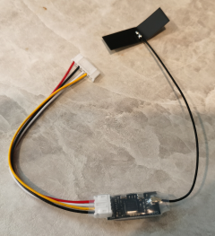
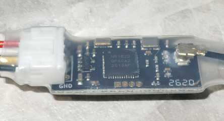
The Bluetooth dongle and ST-Link V2 programmer leads have arrived!

The Bluetooth dongle is compatible with nrf51_vesc ecosystem Makerbase MKS ESC_BT V1.0


The 28AWG leads with connector for ST-Link V2 programmer on the controller side are 7 pins JST GH 1.25


You can crimp that cable leads with this 10 pin 2x5P 2.54mm pitch connector fits ST-Link V2 programmer connector


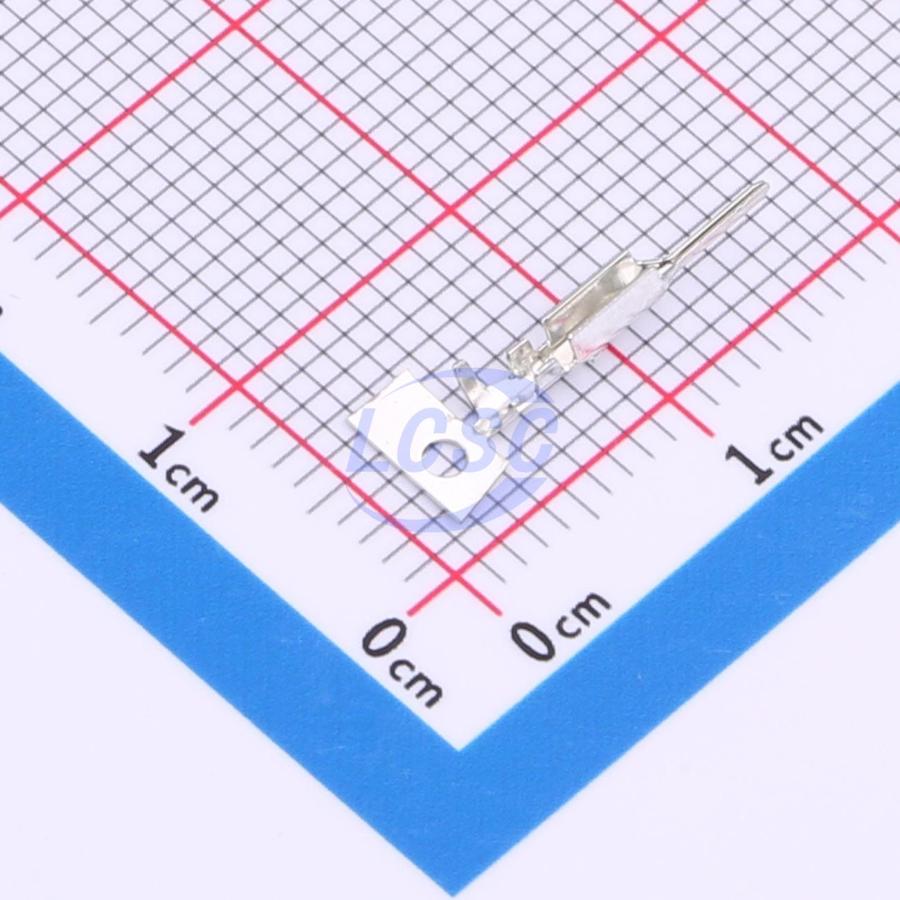
Here are the terminals for this connector fit 28AWG wires


1785801102269.png

1785801746642.png

1785801673508.png

1785801706926.png
 
Last edited:
While we are waiting the controller delivery we can prepare the Bluetooth cable.

You need a 2x2P (4 pin) PHB 2.0 connector and terminals for 26AWG.

2x2P (4 pin) PHB 2.0 connectors can be purchased here


28-24 AWG terminals can be purchased here


1785880088133.png

Chop the original Bluetooth cable terminals off

1785880431186.png

Strip the wires and crimp the PHB 2.0 terminals on the Bluetooth cable. You can use this crimper


1785880549972.png

Attach the wires to the PHB 2.0 connector matching the pins to the Bluetooth module connector pins in the KiCAD schematic

1785881242167.png

1785880707967.png

1785881294002.png
 
Last edited:
The cheap 7 pins JST GH 1.25 cable for firmware flashing fits good and you can use it instead of the more expensive Tag Connect cable to connect an ST Link V2 dongle to flash the firmware.

1785981900979.png
 
Last edited:
The controller has been attached to the motor, and all the cables have been connected. Wish me luck guys because of I am about to plug the battery!

2643174422905.png
 
The moment of truth is here guys! Guess what, we did it again! It works! Unbelievable! From the first try! How it is even possible! Time to celebrate the success!

 
Last edited:
The cadence/torque sensor works! Holy cow! Now we just need to assemble this bad boy, calibrate the rotary encoder, install it on the bicycle and give it a real spin.

 
Last edited:
Alrighty guys, the motor with the INNOTRACE M620 CAN Simple controller has been assembled and the encoder has been calibrated and it it works.

Here is the motor controller installation process. Make sure you flashed the firmware on the controller before installing it to the motor. The firmware file and firmware installation instructions can be found in the "Readme.txt" file in the "M620 CAN Simple Controller\Firmware" folder in the shared archive of the controller files.


1) 3D print the "Rotary Encoder Bumper 3D Print.step" file located in "M620 CAN Simple Controller\Idividual Parts Footprints, Symbols, 3D CAD\Extra parts" folder in the shared archive of the controller files out of high temperature plastic. I used ABS. Glue this bumper to the encoder area on the PCB on with B-7000 glue.

It is not necessary, but it might save your controller if the motor rotor bearing will fail.

The glue can be purchased here


1786059498314.png


1786059437661.png

1786059885370.png

1786059919650.png

2) 3D print the "Insulation.step" file located in "M620 CAN Simple Controller\Idividual Parts Footprints, Symbols, 3D CAD\Extra parts" folder in the shared archive of the controller files out of high temperature plastic. I used ABS. You also can cut this part manually out of 0.4-0.5mm thick sheet of high temperature resistant insulating material (you can use fiberglass boards or fish paper for this purpose)

1786059088483.png

1786059306714.png

2) Glue the insulation on the bottom of the PCB with double sided adhesive tape.

The tape can be purchased here


1786060002106.png

1786060138562.png

3) Cut 2 of 13x34mm rectangular shape thermal pads out of 0.5mm thick thermal pad. Attach those to bottom of the controller in the openings in the insulation and remove the protective layer.

This thermal pad should do it


1786060423220.png


1786060493998.png

4) Attach the controller to the motor case with 3 of M3X5mm screws. I also recommend to apply Loctite 243 blue to those screws before installation.

These screws should work


Loctite 243 can be purchased here


1786060849380.png

1786060934991.png

5) Attach the original Bafang M620 controller green, yellow and blue phase leads to the controller following the color indication on the controller PCB with M3x6x6 terminal block screws. Do not overtighten the screws.

M3x6x6 terminal block screws can be purchased here

https://www.aliexpress.us/item/3256807308404688.html?spm=a2g0o.productlist.main.2.1453fnPdfnPd0K&algo_pvid=6043b8b5-2430-4c81-8cd6-4ee721288407&algo_exp_id=6043b8b5-2430-4c81-8cd6-4ee721288407-1&pdp_ext_f={"order"%3A"328"%2C"eval"%3A"1"%2C"fromPage"%3A"search"%7D&pdp_npi=6%40dis%21USD%213.01%212.93%21%21%2120.21%2119.66%21%40210328df17860617113504682e0ea7%2112000041017461189%21sea%21US%214251763666%21X%211%210%21n_tag%3A-29919%3Bd%3A92cc84d5%3Bm03_new_user%3A-29895&curPageLogUid=UcoYNtQOB1xk&utparam-url=scene%3Asearch%7Cquery_from%3A%7Cx_object_id%3A1005007494719440%7C_p_origin_prod%3A

1786061944719.png

6) Connect the 8 pins connector (display, throttle, brakes) to the receptacle marked "DISP" on the controller PCB. Also connect the 4 pins speed sensor connector (blue, red, green, black bands marked wires on the Bafang M620 CAN harness) to the receptacle marked "SPD" on the controller PCB.

1786062112316.png

7) Attach the battery leads to the controller following the GND (black lead) and B+ (red lead) indications on the controller PCB with M3x6x6 terminal block screws. Do not overtighten the screws. The image below indicates the proper leads routing.


1786062447077.png

8) Connect the Bluetooth dongle to the controller receptacle marked "BLE".

The information for the Bluetooth dongle cable and pinout can be found here


1786062631260.png

9) Place the Bluetooth dongle the way it does not interfere with anything and route the Bluetooth antenna cable outside the motor crossing the motor harness rubber grommet like it is illustrated on the picture below.

1786062869060.png


10) Attach the plastic cowl

1786063038333.png

11) Make sure the motor case gasket is on the motor side case halve. Connect the torque sensor connector to the receptacle on the controller PCB marked "TRQ"

1786063109113.png

12) Connect the motor stator temperature sensor connector to the receptacle on the controller PCB marked "TEMP"

1786063485913.png

Proceed here VESC based INNOTRACE M620 Simple motor controller
 
Last edited:
13) Connect the motor phase leads matching the colors.

1786063672237.png


14) Close the motor case making sure you do not jam the wires or anything else. Make sure the Bluetooth antenna cable goes between the rubber grommet and the gasket

1786063743337.png

1786063856512.png

1786063946312.png


15) Finish the motor assembly tightening the motor case screws.

1786064003049.png

16) Now you can install the motor on your bicycle and calibrate the rotary encoder with VESC Tool application. Make sure the bicycle chain in not on the motor chainring during the rotary encoder calibration.

Important note: if you want to do motor parameters detection make sure the display is set to Eco support mode (if the display will be set in any higher support mode some motor parameters will be detected wrong and the walk assist mode will not work properly causing the motor acceleration. If the display will be set in no support mode or walk assist mode the motor detection will not work at all). For rotary encoder calibration the display can be set to any support mode (no support mode and walk mode will not allow you to calibrate the rotary encoder).
 
Last edited:
Swapping the good old INNOTRACE Shrimp on the new INNOTRACE M620 CAN Simple

1786149601735.png

The Bluetooth antenna can freely hang between the motor and the frame

1786150704058.png
 
Last edited:
Just took it for a spin and it works beautifully!

The motor max temperature I saw was 85C after long uphill at full power. The controller temperature at the same time was not higher than 40C.

1786168434607.png

The power settings are 80A 14S 52V battery, 150A motor current, 280A absolute maximum current, 4100W maximum wattage.

1786168602404.png

1786168664531.png

So I highly recommend you this motor controller and you better pair it with 80-100A 16-20S battery to squeeze maximum out of it.

I will post updated files later but there are no changes to the PCB and PCB assembly files so you can use the existing files to purchase or make the controller.

1786168908874.png
 
Last edited:
@TPEHAK-how can a 0% electronic assembly know how person BUY one of this controller
The instructions for such person about how to buy controllers are posted here


That person needs to find parts replacements in case of some pars are out of stock though using the JLCPCB interface and inspect the pars positions and orientation (even the pars were placed and positioned properly when I ordered the controllers) and fix it if necessary using the JLCPCB interface. There is a lot of YouTube videos about how to do this so that person can also watch those videos. If that person is not sure about something that person can post questions here.
 
Last edited:
So.. that's it? No bugs/problems? Nothing to improve in the first iteration? 😷🥸
 
Back
Top