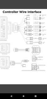
Votol EM-100 & EM-150 controllers

Is power actually shutting off to the system, or is the controller simply ceasing to respond to control inputs?

The former indicates the BMS is shutting off it's output; the latter indicates the controller is hitting some form of LVC (there are often multiple levels of this in programmable controllers, and in smart BMSs).

If you don't want the controller to do any shutoff, you should set it's LVC below anything the pack would ever drop to.

If you do this, you should set the BMS LVC to be well above what it normally would be, so you aren't as hard on the cells, since the normal BMS LVC is intended to protect them from damage as a very last resort. The controller LVC is intended to provide everyday "empty battery" protection, so it's usually set a fair bit higher.

Also, the controller may have a better LVC protection layer that lets it just rollback power usage as it approaches LVC, so you can better use what capacity the battery still has as it gets closer to empty.

If you leave this up to the BMS, then it's just going to shut off output when it reaches LVC, since it's hardware can't do anything else.


You also need to set the controller's current limit to *below* what the battery is designed and able to handle, because it is the part of the system that is designed and built to limit current to prevent damage to the battery, etc., and it will do it in a graceful way that just rolls back motor power when it reaches this limit to hold it there, but let the system still run.

If you leave that up to the BMS, then the BMS will just cut power to the system when it's current limit is exceeded, since it's hardware can't do anything else.

For example, with a controller current limit of 200A, but a battery only capable of 150A peak and 120A continuous, the BMS doesn't have any choice but to shutdown whenever the controller pulls that 200A, which can happen in very short peaks that don't show up on your display/etc.


What usually causes the problem you describe is the battery being unable to handle the load, and sagging significantly in voltage. How the system responds to that depends on the BMS and controller design and settings.

If the sag is enough to trigger the BMS LVC, power will shut off, often requiring a power cycle to recover (sometimes requiring a charge cycle to be started or even completed before it will reset).

If the sag is only enough to trigger the controller LVC, it will just stop responding to control inputs until the voltage recovers enough to be above LVC--but as soon as the load is reapplied to cause it to sag that much again, it will stop responding again.

If the controller has a rollback-power feature as it approaches LVC, then the sag will just cause it to provide less power in response to the same control inputs, so it doesn't make the sag any worse.
 
Last edited:
Is power actually shutting off to the system, or is the controller simply ceasing to respond to control inputs?

The former indicates the BMS is shutting off it's output; the latter indicates the controller is hitting some form of LVC (there are often multiple levels of this in programmable controllers, and in smart BMSs).

If you don't want the controller to do any shutoff, you should set it's LVC below anything the pack would ever drop to.

If you do this, you should set the BMS LVC to be well above what it normally would be, so you aren't as hard on the cells, since the normal BMS LVC is intended to protect them from damage as a very last resort. The controller LVC is intended to provide everyday "empty battery" protection, so it's usually set a fair bit higher.

Also, the controller may have a better LVC protection layer that lets it just rollback power usage as it approaches LVC, so you can better use what capacity the battery still has as it gets closer to empty.

If you leave this up to the BMS, then it's just going to shut off output when it reaches LVC, since it's hardware can't do anything else.


You also need to set the controller's current limit to *below* what the battery is designed and able to handle, because it is the part of the system that is designed and built to limit current to prevent damage to the battery, etc., and it will do it in a graceful way that just rolls back motor power when it reaches this limit to hold it there, but let the system still run.

If you leave that up to the BMS, then the BMS will just cut power to the system when it's current limit is exceeded, since it's hardware can't do anything else.

For example, with a controller current limit of 200A, but a battery only capable of 150A peak and 120A continuous, the BMS doesn't have any choice but to shutdown whenever the controller pulls that 200A, which can happen in very short peaks that don't show up on your display/etc.


What usually causes the problem you describe is the battery being unable to handle the load, and sagging significantly in voltage. How the system responds to that depends on the BMS and controller design and settings.

If the sag is enough to trigger the BMS LVC, power will shut off, often requiring a power cycle to recover (sometimes requiring a charge cycle to be started or even completed before it will reset).

If the sag is only enough to trigger the controller LVC, it will just stop responding to control inputs until the voltage recovers enough to be above LVC--but as soon as the load is reapplied to cause it to sag that much again, it will stop responding again.

If the controller has a rollback-power feature as it approaches LVC, then the sag will just cause it to provide less power in response to the same control inputs, so it doesn't make the sag any worse.
Thank you for the reply, i dont think its a max amps thing because on a full battery it can pull maximum power repeatedly without issue.

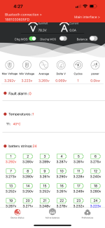
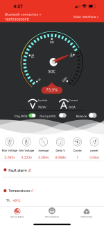
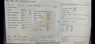
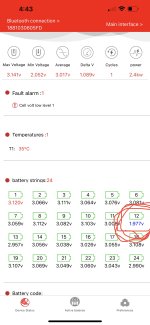
As for voltage sag, that’s entirely possible but i dont see the sagging voltages on my BMS app. Take a look at my screenshots of the BMS app at the time the controller shut off. As you can see in the configuration screenshot i have the undervoltage cutoff at 63 and over at 90, same for the cells they are set to 1.4 for cuttoff and the controller cant tell where the cells are anyway. also on the BMS there are fault alarms.

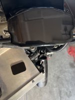
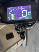
At the moment i took those screenshots the screen to the controller had shut off (took a picture of it on and off) and there was no light on the controller. (the little led on the back was off not red)

So would you guess that the BMS is shutting off output? wouldn’t it throw a fault or alarm? Theres no excessive cell voltage variation. I watch the cells as i ride and don’t see them sagging, does any one know of the Daly BMS updates enough to show momentary voltage sagg?

Last thing that may be a lead, when it shuts off as it is in the pictures. it doesn’t matter how long i disconnect power, the controller never comes back on until i put it on the charger. how could voltage sag which returns to 78v stable not turn the controller back on when i reconnect it?
 

Attachments

  • 0357F79A-89CF-4EEA-93E2-ADF90FBAAD9A.png
    0357F79A-89CF-4EEA-93E2-ADF90FBAAD9A.png
    658 KB · Views: 35
  • 8AB998CA-31D7-4159-B106-12F78DCF67DA.png
    8AB998CA-31D7-4159-B106-12F78DCF67DA.png
    843.8 KB · Views: 46
  • 04AC0699-7B98-46DA-9F24-A88886698708.jpeg
    04AC0699-7B98-46DA-9F24-A88886698708.jpeg
    2.2 MB · Views: 47
  • image.jpg
    image.jpg
    1.5 MB · Views: 45
  • image.jpg
    image.jpg
    1.3 MB · Views: 26
Last edited:
Before I get into the details below, since this is not a controller-specific problem, is it ok if I split your posts and my replies off to a separate troubleshooting thread? (best to move them to your build thread if you have one).

Thank you for the reply, i dont think its a max amps thing because on a full battery it can pull maximum power repeatedly without issue.

As for voltage sag, that’s entirely possible but i dont see the sagging voltages on my BMS app. Take a look at my screenshots of the BMS app at the time the controller shut off. As you can see in the configuration screenshot i have the undervoltage cutoff at 63 and over at 90, same for the cells they are set to 1.4 for cuttoff and the controller cant tell where the cells are anyway. also on the BMS there are fault alarms.

1.4v is VERY low, below typical minimums, for a LiFePO4 cell. 2.5v is typically basically empty, and setting above that point, more like 2.8v or higher, is a better idea as it will have less stress on it. 2.1v or so is the lowest I would use if I absolutely had to...but I would use 3v myself to improve pack longevity by reducing stress.

Similarly, 3.4v is really "full" for LFP cells; the capacity between there and 3.6v that they are usually charged to (for balancing) is so small it would be better to leave that and charge lower, for less cell stress and greater longevity. So 90V as overvoltage is high; even at 3.65v/cell (typical balancing / full voltage) for 24 cells, that's only 87.6v.

Less stress means less change of each cell vs other cells over time, and they'll stay balanced better over time, too. (the further they are discharged, the more stressed and unbalanced they will be each time, and the longer a charge cycle will take trying to fix that).


I recommend looking at the specification sheet for the cells you used; this is available from the manufacturer of the cells. (if they don't have these, then you have no certain data about / specifications of the cells and will have to determine all their limits experimentally to be able to properly setup your BMS and controller for them--it also probably means they don't hold their cells to any standard and so every cell could be radically different from every other, so any pack of cells won't be matched in characteristics to each other, and the pack won't perform as well as it would if they were all the same (unless the pack builder tests every cell and discards all cells that don't match each other, which can mean buying many times the amount of cells the pack actually needs).

For a 24s pack, at 2.8v per cell, that gives a pack-level LVC of 67.2v (at the BMS); I recommend something higher at the controller (2.9v/cell 69.6v, or 3v/cell, 72v), but the 67.2v at lowest.

If the controller is set for 67.2v LVC, then set the BMS for a tiny bit lower, like 66.5v or something (whatever the per-cell voltage is for that), so that the BMS won't shut off before the controller has the chance to just release the load. Otherwise you're going to have power cuts on every throttle up when the battery is near empty, because the BMS will cut all power.


If you can provide details about the cells, pack build, BMS, etc., it may help diagnose the problem and suggested settings or repairs to correct it.


At the moment i took those screenshots the screen to the controller had shut off (took a picture of it on and off) and there was no light on the controller. (the little led on the back was off not red)

So would you guess that the BMS is shutting off output?
If there's no voltage out of the BMS to the controller (actually measured with a meter external to the battery, not just displayed on the BMS program), then the BMS has shut off to protect the cells.

That means that some parameter in the BMS was exceeded (or there is a fault in the BMS itself). If the BMS software doesn't show you what that is, you'd have to measure things yourself during these events, using multimeters or cell monitors, and watch it realtime under load to see what happens. If the event that cuases the shutoff is short enough, you may not see it realtime because of the way meters read and display their data. It might require a reasonably fast multicell logging device to catch, and then see in the logs what happened. This isnt' normally needed; there are other ways to check things.


wouldn’t it throw a fault or alarm? Theres no excessive cell voltage variation. I watch the cells as i ride and don’t see them sagging, does any one know of the Daly BMS updates enough to show momentary voltage sagg?

You'd need to look at any logging info the BMS takes. If it doesn't log the maximum cell voltage difference, or the minimum cell voltages, etc., you'll have to use other methods to find the problem. These smart BMSs generally have some form of logging, even if it is only a simple record on screen of what the highest and lowest cell voltages were, which cell that was, what the highest and lowest currents were, etc.

But first I'd recommend setting the cell limits (votlage, current, etc) to something closer to what such cells are normally designed to handle.

The display you see is probably massively delayed from realtime, and updated very few times per second (or even slower). First the BMS has to read the cells, then process teh data, then encode the data for sending over BT to your phone, then your phone processes that incoming BT stream, sends it to the app it's for, the app has to decode the data stream, process it, and then display it. So it's not unusual to not see voltage sag in some cases like this, especially if the sag is short. (always if the sag is shorter than the display update interval).


Last thing that may be a lead, when it shuts off as it is in the pictures. it doesn’t matter how long i disconnect power, the controller never comes back on until i put it on the charger. how could voltage sag which returns to 78v stable not turn the controller back on when i reconnect it?

Where is the 78v measured, and how?

If it is just displayed on the BMS app, that means the BMS reads that voltage. It doesn't mean it's actually present on it's output.

If it's measured at the controller input, then the controller *is* turned back on (or rather, it has power and could be turned on, if whatever turns it on is engaged).

Also, when disconnected from a load, a BMS's FETs can show a voltage on their output as a "ghost" or "leakage" but when the load is applied, this voltage drops to usually nothing.

If the BMS won't turn it's output back on until it's placed on a charger, it probalby means a cell or cells dropped so low in voltage that the BMS's settings indicate the cells would be damaged if further discharge was allowed without recharging them first.

At some point those cells will probably drop far enough that the BMS will even refuse to charge them, because a cell that goes too low is permanently damaged and can be a fire hazard.
 
Regarding the screenshots and readouts:

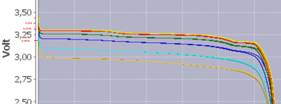
LFP has a very flat discharge curve, so a tiny difference in voltage between cells means a significant capacity difference (or rather, difference in SoC, state of charge).

I attached a graph of a random LFP cell off the Lygte.info.dk testing site, original here:
zoomed in and edited to show some finer voltage gradations; if you follow those across the chart you'll see how the cell voltage drops as capacity decreases (I think the actual capacity numbers are cut off, but they are about 250mAh per vertical line, for an 1800mAh cell, totally empty at far right as the curves all reach the bottom at 2.0v

You can put lines on there for your cell voltages to see the possible difference in capacity percentage between the ones with different voltages (you might have to zoom it in farther).

Basically what I'm trying to show is that your cells are not perfectly balanced (even if they match voltages at full charge), they don't match each other in state of charge / capacity (probably internal resistance too), and so they are discharging at different rates, and will also sag at different rates and amounts. The ones with the lowest voltage have the lowest charge amount and will probably sag more under less load than the others. It's likely that this sort of problem is causing your system issue, but you'll have to test in a way that you can see this happening to be sure, or repair the battery so it is operating correctly and then retest the system.


Regarding the controller setup screenshot:

I see an HVC (overvoltage) of 89.5v, which is high for this pack; the pack should be full at 87.6v or less.

THe LVC (undervoltage) is 63v, whihc would be way too low--the cells would be beyond empty, and would be damaged, if the controller was the only cut off (like if the BMS failed to shutdown due to FET failure or software problems), at that voltage. I'd set that to something like 69.6 or even 72v.

The soft undervoltage, where the controller begins to limit power usage to minimize load on the nearly-empty battery, at 66v is also too low; it wouldn't cause damage but it won't give the system any leeway to protect the cells. I'd set that to something like 72v or higher.
 

Attachments

  • Soshine 18650 LiFePO4 1800mAh (Black)-Capacity.png
    Soshine 18650 LiFePO4 1800mAh (Black)-Capacity.png
    367.8 KB · Views: 2
Ja, das macht das Testverfahren – es findet die richtige Phase/Hall-Kombination, um den Motor ohne übermäßige Stromaufnahme zu betreiben (was zu einer Überhitzung des Motors führt).

Eine weitere Ursache für eine Motorüberhitzung ist ein Motor, der die darauf aufgebrachte Last nicht bewältigen kann, oder ein falsches Getriebe zwischen Motor und Boden für die Geschwindigkeit, mit der er betrieben wird, im Vergleich zum Gelände/der Last. Oder unzureichende Kühlung (z. B. Gehäuse um den Motor usw.).

Wenn der Controller eine tatsächliche Winkeleinstellung für die Hallen hat, können Sie sich beim Motorhersteller erkundigen, wo sie installiert wurden, aber normalerweise sind es 120. 60-Grad-Hallen sind nicht sehr verbreitet.

Warum sie es einen "Hall-Winkel"-Test nennen, weiß ich nicht, weil es nicht den Hall-Winkel bestimmt, sondern die richtige Hall-Phasen-Kombination (bei anderen Controllern nennen sie es normalerweise "Selbstlernen", aber Kelly fing an zu rufen es "Hallwinkel identifizieren" und das hat die Dokumentation anderer Unternehmen infiziert ....


Sie könnten theoretisch einen Motor mit vorgezogenem oder verzögertem Timing haben (nicht neutrale Platzierung der Sensoren, sodass sie vorwärts anders laufen als rückwärts, was spezielle Steuerungen mit Einstellungen erfordert, um dies zu kompensieren, um korrekt zu funktionieren, aber diese sind selten.)

Wenn Sie diesen Winkel tatsächlich manuell finden müssen, benötigen Sie wahrscheinlich ein Oszilloskop, um den Hallsignalausgang mit dem Phasensignaleingang zu vergleichen. Sie reihen sich normalerweise aneinander, sodass der Betrag der Zeitdifferenz in Grad umgewandelt werden kann, wenn man weiß, wie viele Grad jeder Magnet um den Rotor herum einnimmt, im Vergleich zu wie viele Änderungen in einem Phasenzyklus vorgenommen werden usw. (Entschuldigung, ich weiß es nicht wie man die Mathematik dafür ausdrückt). Es gibt einige Threads zum Design von Motorsteuerungen mit Scope-Bildern, die das typische Timing zeigen, das Sie sehen sollten.
Exakt! Und dafür gibt es in der votol-Software die Einstellung "hall shift". Dafür gibt es eine Selbstlernfunktion.


(english version:

Exactly! And that's what the "hall shift" setting is for in the votol software. There is a self-learning function for this.

attached pdf is the instructions for that self-learning function)
 
while doing VOTOL controller programming what are the major changes we have to do in port settings?
what about PD0, JTCK,SWD, PA11...define all these columns please..?
 
Hi All,

I have watched this post for quite some time, it has been really helpful and has enabled me to interpret the manual better for sure!

I have run into a couple of problems. Mostly of my own doing, which I am hoping someone on here has either experienced or has a better grasp of this than me.

Firstly the hardware.

Controller: Votol EM150SP with Can
Motor: QS 3KW Mid Drive older style without the two flanged mounts
Throttle: SiaEcosys 0-5v
Battery: 72v 20ah on Anderson connections with BMS (used for testing)

When originally setting this up, using the factory settings all was well. The bike was doing all of the things i'd have expected it to do. The only issue I found was that it really wasn't pulling as well as i'd expected.

After reading through these forums I found the settings that I felt was best for my setup and changed them on the controller. !HOWEVER! I did not take a backup of the original settings. I didn't feel it was necessary at the time because the only thing I changed was the busbas current and flux weakening values.

The problem is that when updating the settings it seemed to knock out a bunch of other settings that I had. The throttle voltage settings changed to some randomly low numbers I think they were 0.2 in each area and the hall shift angle moved to 0. I know it wasn't zero but I can't remember now if it was 60 or 120. The specs say 120 but the motor does not sound happy at 120.

I then tried to test the setup with my attached settings (to the best of my memory and having read through the manual to ensure parameters are correct) but the bike will not move forward in low mid or high modes. It will ONLY turn the wheel in 'S' mode. In the other modes you can hear the motor want to start but it just won't.

Please if anyone can provide advice I would very much appreciate it.

Thanks,

View attachment 267555View attachment 267556View attachment 267557View attachment 267558View attachment 267559
Mention the detailed information about SW, HW,BUADRATE
 
Before I get into the details below, since this is not a controller-specific problem, is it ok if I split your posts and my replies off to a separate troubleshooting thread? (best to move them to your build thread if you have one).


1.4v is VERY low, below typical minimums, for a LiFePO4 cell. 2.5v is typically basically empty, and setting above that point, more like 2.8v or higher, is a better idea as it will have less stress on it. 2.1v or so is the lowest I would use if I absolutely had to...but I would use 3v myself to improve pack longevity by reducing stress.

Similarly, 3.4v is really "full" for LFP cells; the capacity between there and 3.6v that they are usually charged to (for balancing) is so small it would be better to leave that and charge lower, for less cell stress and greater longevity. So 90V as overvoltage is high; even at 3.65v/cell (typical balancing / full voltage) for 24 cells, that's only 87.6v.

Less stress means less change of each cell vs other cells over time, and they'll stay balanced better over time, too. (the further they are discharged, the more stressed and unbalanced they will be each time, and the longer a charge cycle will take trying to fix that).


I recommend looking at the specification sheet for the cells you used; this is available from the manufacturer of the cells. (if they don't have these, then you have no certain data about / specifications of the cells and will have to determine all their limits experimentally to be able to properly setup your BMS and controller for them--it also probably means they don't hold their cells to any standard and so every cell could be radically different from every other, so any pack of cells won't be matched in characteristics to each other, and the pack won't perform as well as it would if they were all the same (unless the pack builder tests every cell and discards all cells that don't match each other, which can mean buying many times the amount of cells the pack actually needs).

For a 24s pack, at 2.8v per cell, that gives a pack-level LVC of 67.2v (at the BMS); I recommend something higher at the controller (2.9v/cell 69.6v, or 3v/cell, 72v), but the 67.2v at lowest.

If the controller is set for 67.2v LVC, then set the BMS for a tiny bit lower, like 66.5v or something (whatever the per-cell voltage is for that), so that the BMS won't shut off before the controller has the chance to just release the load. Otherwise you're going to have power cuts on every throttle up when the battery is near empty, because the BMS will cut all power.


If you can provide details about the cells, pack build, BMS, etc., it may help diagnose the problem and suggested settings or repairs to correct it.


If there's no voltage out of the BMS to the controller (actually measured with a meter external to the battery, not just displayed on the BMS program), then the BMS has shut off to protect the cells.

That means that some parameter in the BMS was exceeded (or there is a fault in the BMS itself). If the BMS software doesn't show you what that is, you'd have to measure things yourself during these events, using multimeters or cell monitors, and watch it realtime under load to see what happens. If the event that cuases the shutoff is short enough, you may not see it realtime because of the way meters read and display their data. It might require a reasonably fast multicell logging device to catch, and then see in the logs what happened. This isnt' normally needed; there are other ways to check things.


You'd need to look at any logging info the BMS takes. If it doesn't log the maximum cell voltage difference, or the minimum cell voltages, etc., you'll have to use other methods to find the problem. These smart BMSs generally have some form of logging, even if it is only a simple record on screen of what the highest and lowest cell voltages were, which cell that was, what the highest and lowest currents were, etc.

But first I'd recommend setting the cell limits (votlage, current, etc) to something closer to what such cells are normally designed to handle.

The display you see is probably massively delayed from realtime, and updated very few times per second (or even slower). First the BMS has to read the cells, then process teh data, then encode the data for sending over BT to your phone, then your phone processes that incoming BT stream, sends it to the app it's for, the app has to decode the data stream, process it, and then display it. So it's not unusual to not see voltage sag in some cases like this, especially if the sag is short. (always if the sag is shorter than the display update interval).


Where is the 78v measured, and how?

If it is just displayed on the BMS app, that means the BMS reads that voltage. It doesn't mean it's actually present on it's output.

If it's measured at the controller input, then the controller *is* turned back on (or rather, it has power and could be turned on, if whatever turns it on is engaged).

Also, when disconnected from a load, a BMS's FETs can show a voltage on their output as a "ghost" or "leakage" but when the load is applied, this voltage drops to usually nothing.

If the BMS won't turn it's output back on until it's placed on a charger, it probalby means a cell or cells dropped so low in voltage that the BMS's settings indicate the cells would be damaged if further discharge was allowed without recharging them first.

At some point those cells will probably drop far enough that the BMS will even refuse to charge them, because a cell that goes too low is permanently damaged and can be a fire hazard.
AmberWolf,
Fantastic info, really helped my understanding and trouble shooting. With your help i did find the problem and it wasn’t the controller. we can move this thead.

I hooked up a volt meter as i rode and was able to see that it did cut off output from the battery even though it still had plenty of power. I assumed that since it still has power it would output it once whatever went low recovered. However, voltage remained 0 on the meter as i was looking at 78v on the BMS app. So i went digging through the BMS app and found a reset button which was awesome and allowed me to bring it back on line.

This process combined with changing the delta shut off limits allowed me to see the following…. (see the attached picture) One of my cells is weak.

Thank you so much for helping me find this!
 

Attachments

  • B190D6FE-0A80-4398-B004-2F461CAC1111.jpeg
    B190D6FE-0A80-4398-B004-2F461CAC1111.jpeg
    345.2 KB · Views: 23
Has anyone had luck adjusting the voltage in the dkd display? Never reads full and still shows 2-3 bars as 25%. Using the 60v setting with a 16s battery
 
View attachment 332112Привет еще раз, я не уверен в значениях ослабления потока. Записал видео работы двигателя:

[МЕДИА=youtube]9OZLzy64tA0[/МЕДИА]

Кстати, самообучение работает некорректно. Направление не меняется, когда я перезапускаю сигнал зажигания, когда разъем парковки закорочен. Двигатель вращается на один оборот, но каждый раз в одном и том же направлении. И угол зала не меняется, когда я пробую разные ваули. Есть ли у вас какие-либо идеи? Заранее спасибо.
Измените «PAIS» на «22:LY_e_gear» и поставьте «L». Далее "param write" и далее все по инструкции.... У меня все заработало на «PAIS».
 
View attachment 332112Hi again, I am not sure about the values of flux weakening. I have recorded a video of the motor spining:


By the way, self learning is not working properly. The direction doesn't change when I restart the ignition signal when the park connector is shorted. The motor spins one turn but the same direction every time. And the hall angle doesn't change when I try different vaules. Do you have any idea? Thanks in advance.
Change the “PAIS” setting to “22:LY_e_gear“ and enable the ”L" option. Then click on the “param write" button. . Turn off the upper computer when you receive a notification about the successful recording of parameters. After that restart the electric door lock
Step 4: The motor will automatically start rotating slowly for one lap. If the direction of rotation of the engine is opposite to the direction of rotation of the car, it is necessary to start the electric lock again for self-learning. Follow the instructions..... In my case, everything worked on “PAIS”
 
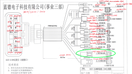
What would I connect the purple/grey wire to? The manual says it's for high braking but there isn't a negative beside it like the other connectors.
 

Attachments

  • Screen Shot 2023-04-13 at 8.02.58 AM.png
    Screen Shot 2023-04-13 at 8.02.58 AM.png
    2.8 MB · Views: 24
What would I connect the purple/grey wire to? The manual says it's for high braking but there isn't a negative beside it like the other connectors.
What controller? On the em150 the purple is high brake so 12v and the purple with the gray strip is the keyed battery power to turn it on and off
 

Attachments

  • Screenshot_20230308-064934.png
    Screenshot_20230308-064934.png
    205.7 KB · Views: 21
Does anyone have the self learning .bin file?
According to QS motor the em150 doesn't have a hall angle self learn. Does anyone have any tricks or guides to figure it out?

You don't need .bin file. self learning goes like in this video, but it works without that .bin file also.

self learning

You just need to do that reset once and then connect and save parameters. I don't know why this guy do it 3-times.
 
Last edited:
Hi All,

I have watched this post for quite some time, it has been really helpful and has enabled me to interpret the manual better for sure!

I have run into a couple of problems. Mostly of my own doing, which I am hoping someone on here has either experienced or has a better grasp of this than me.

Firstly the hardware.

Controller: Votol EM150SP with Can
Motor: QS 3KW Mid Drive older style without the two flanged mounts
Throttle: SiaEcosys 0-5v
Battery: 72v 20ah on Anderson connections with BMS (used for testing)

When originally setting this up, using the factory settings all was well. The bike was doing all of the things i'd have expected it to do. The only issue I found was that it really wasn't pulling as well as i'd expected.

After reading through these forums I found the settings that I felt was best for my setup and changed them on the controller. !HOWEVER! I did not take a backup of the original settings. I didn't feel it was necessary at the time because the only thing I changed was the busbas current and flux weakening values.

The problem is that when updating the settings it seemed to knock out a bunch of other settings that I had. The throttle voltage settings changed to some randomly low numbers I think they were 0.2 in each area and the hall shift angle moved to 0. I know it wasn't zero but I can't remember now if it was 60 or 120. The specs say 120 but the motor does not sound happy at 120.

I then tried to test the setup with my attached settings (to the best of my memory and having read through the manual to ensure parameters are correct) but the bike will not move forward in low mid or high modes. It will ONLY turn the wheel in 'S' mode. In the other modes you can hear the motor want to start but it just won't.

Please if anyone can provide advice I would very much appreciate it.

Thanks,

View attachment 267555View attachment 267556View attachment 267557View attachment 267558View attachment 267559
can you define the port settings and why we are choosing that particular options...?
 
You don't need .bin file. self learning goes like in this video, but it works without that .bin file also.

self learning

You just need to do that reset once and then connect and save parameters. I don't know why this guy do it 3-times.
The software I have doesn't have the option to reset like show in the video
 
Back
Top