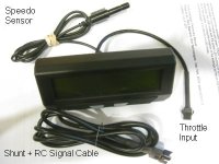
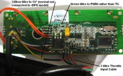
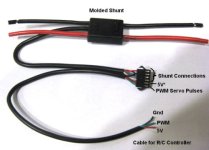
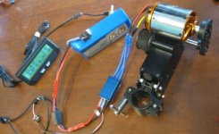
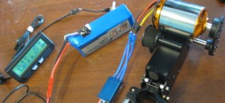
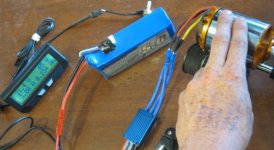
It occurred to me quite some time ago that we could potentially use the CA's PWM output to directly drive R/C style motor controllers rather than just generating an analog voltage for ebike controllers. The nice folks at FFR trikes have encouraged the issue so in the latest Rev11 CA board, there is a new pad in the upper left labelled "PWM" which is designed to be a servo style 1-2mS pulse feed for RC speed controls.
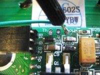
Anyways, I've been playing around with the software for this and am trying to work out a new model of RC compatible Cycle Analyst, and would appreciate both feedback and beta testers since I don't have that much first hand familiarity with RC ebike builds.
What we have right now is this, Beta V2.24 firmware:
View attachment 6
In the advanced menu, there is now an option for selecting the throttle output mode, between Volts (vlt) or R/C servo pulese (R/C):
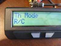
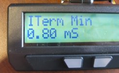
If you select the R/C mode, then the upper and lower bounds of the throttle output instead of being settable between 0-5V, are now settable between 0-5 mS. So for an RC controller, we'd set ITermMin to about 0.8 mS and ITermMax to about 2mS. If you wanted to put a cap on the upper speed or motor RPM limit, then ITermMax could be tweaked lower:
View attachment 3
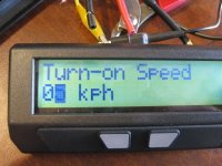
As well, since the sensorless R/C controllers often have startup issues at low speeds, there is a new option for a low speed cutout. So the controller won't be engaged until the bike reaches a programmable threshold speed, to ensure a smooth motor start. Naturally this feature is effectively disabled if the turn-on speed is set to 0:
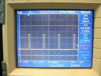
Once these things are done, then the output on the PWM pad is a 0.8-2.0 mS pulse every 25 mS, which should be able to feed into the speed control input of any RC controller. The CA would need to be setup with the AuxVoltage function enabled, typically as a current limit. So basically you would feed a standard ebike hall effect throttle to the Vi pad of the CA to tell the CA what the desired current is, and then the CA would output a pulse stream to the RC controller varying the pulse width in order to achieve this setpoint current.

Anyways, I've been playing around with the software for this and am trying to work out a new model of RC compatible Cycle Analyst, and would appreciate both feedback and beta testers since I don't have that much first hand familiarity with RC ebike builds.
What we have right now is this, Beta V2.24 firmware:
View attachment 6
In the advanced menu, there is now an option for selecting the throttle output mode, between Volts (vlt) or R/C servo pulese (R/C):

If you select the R/C mode, then the upper and lower bounds of the throttle output instead of being settable between 0-5V, are now settable between 0-5 mS. So for an RC controller, we'd set ITermMin to about 0.8 mS and ITermMax to about 2mS. If you wanted to put a cap on the upper speed or motor RPM limit, then ITermMax could be tweaked lower:

View attachment 3
As well, since the sensorless R/C controllers often have startup issues at low speeds, there is a new option for a low speed cutout. So the controller won't be engaged until the bike reaches a programmable threshold speed, to ensure a smooth motor start. Naturally this feature is effectively disabled if the turn-on speed is set to 0:

Once these things are done, then the output on the PWM pad is a 0.8-2.0 mS pulse every 25 mS, which should be able to feed into the speed control input of any RC controller. The CA would need to be setup with the AuxVoltage function enabled, typically as a current limit. So basically you would feed a standard ebike hall effect throttle to the Vi pad of the CA to tell the CA what the desired current is, and then the CA would output a pulse stream to the RC controller varying the pulse width in order to achieve this setpoint current.


