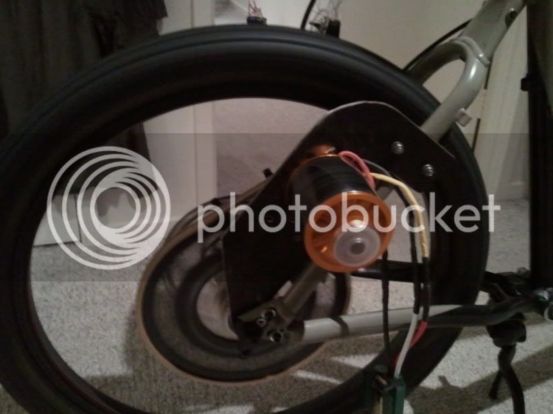
I safely received my CD-LRC, and just got a chance to wire it up and try it out on my
Commuter Booster. And it works ! Yah.
Here is what I had to do to get it up and running.
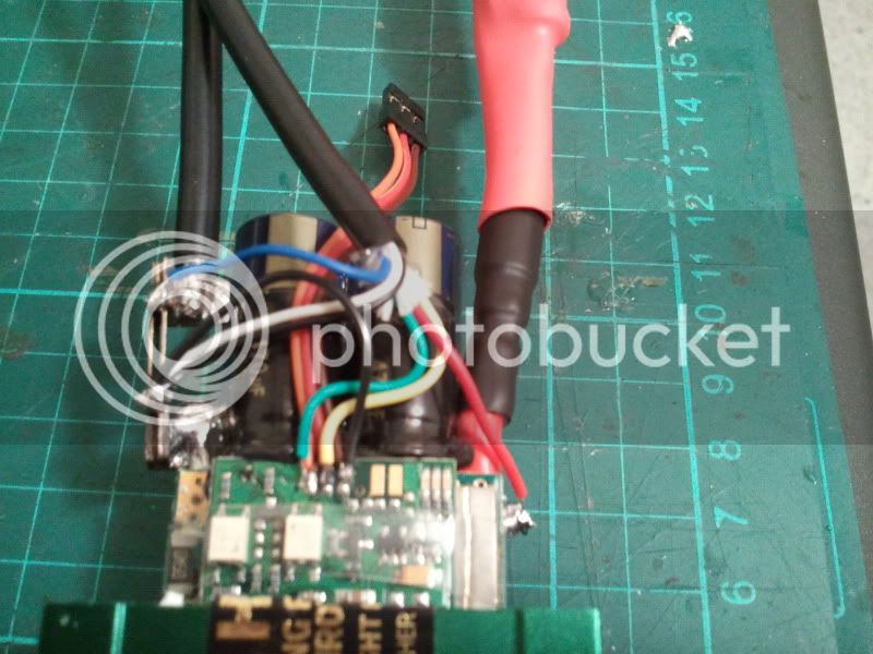
- put some Anderson PP on the molded shunt
- put a servo connector on the throttle out wire
- connect everything up on the bike
- adjust a few settings (wheel size, Low Volts Limit, ITerm Min)
Too easy.
Here are my notes:
(1) Large Screen
- this is the first large screen CA I have seen, and it is huge.
- I think I prefer the smaller screen size for an ebike. But that is just my preference.
(2) Backlight
- The back light seems to dim when the ESC is turned on.
- My ESC has a BEC so I assume this has something to do with the 5.5V on the throttle out line becoming active
(3) Throttle Out PWM
- PWM loop cycle was measured at 40Hz, so 25ms loop cycle appears to be accurate.
- but PWM pulse widths appears to be a little off.
- I had ITerm Max @ 2.00 ms, and ITerm Min @ 1.10 ms, but measured 2.10ms & 1.16ms with my osciloscope.


(4) Hall Throttle
- disconnecting the hall throttle input, makes the drive go full throttle

- disconnecting the hall throttle input, and turning the ESC off (so no 5V supplied) makes the CA screen contrast go weird, making the screen difficult to read.


- There is a lot of dead range on the hall throttle at both bottom end and top.:
--- 0-30% rotation = zero throttle
--- 30-50% rotation = 0-100% throttle
--- 50-100% rotation = 100% throttle
(5) Throttle response
- is very rapid with default settings
- I haven't adjusted the settings yet.
(6) Shunt
- Current readings appear to be off. This is a comparison between CA display, and readings by a DMM
---- (zero throttle) CA = 0.21A , DMM = 0.098 Amps
---- (full throttle) CA = 5.3A, DMM = 3.70 Amps
- Set RShunt = 1.000mOhm
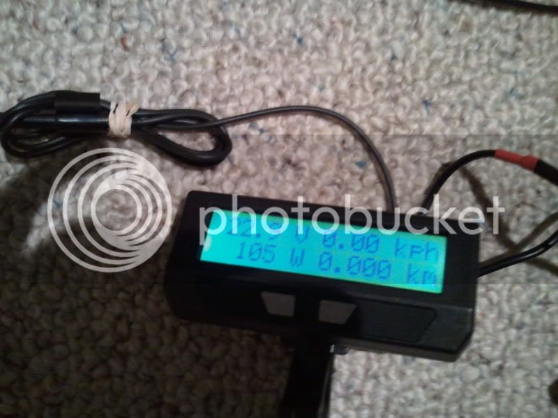
(7) Volts
- Volt readings seem about right.
- CA = 19.1 V
- Turnigy Watt Meter = 19.27 V
- DMM = 19.25 V
So my questions are:
(1) Can I adjust the input throttle range to suit the hall throttle?
(2) The current readings seem to be out by a fair way. Should I just zero the amps, test again, and adjust the RShunt value accordingly?
- Adrian

") . Linked shifting between two nuvinci's isn't in principle a problem, it's more the weight of two Nuvinci's that I wanted to avoid. So the ability to achieve reverse pedal torques with a single overruning clutch rather than an entire 2nd hub seems like a great plan, even if it means that the reverse direction gearing is of a fixed ratio.
. Linked shifting between two nuvinci's isn't in principle a problem, it's more the weight of two Nuvinci's that I wanted to avoid. So the ability to achieve reverse pedal torques with a single overruning clutch rather than an entire 2nd hub seems like a great plan, even if it means that the reverse direction gearing is of a fixed ratio.