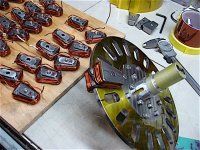
APL's DIY axial-flux motor

The Macor isn't a bad deal, at $20. for 3", it might be all that I need. But I would need to shape and cut small pieces
off, so I guess it depends on what they mean by machinable,.. any idea on what kind of lathe tooling is used for that?

I haven't worked with ceramics at all, but it seems to me that if I can grind a slight taper on the beads shown above,
then I would be all set to go. Just drill a slightly smaller hole, and pound them in.

I'll have to try some experiments with the pins that I have, and see if I can grind them a bit with the bench grinder, I have
one with a really fine stone on it. Otherwise, perhaps one of the diamond discs they sell for common tools might work.
Worth a try.
 
I tried working some ceramic today, and found that a diamond disc will do the job fairly well, so now it's a matter of
finding the best disc for the job, and working out a method to taper the pins. So that's good news, and moves things
forward a little more, since at least I have that option now.

I also found out that a #18 drill bit has a diameter of .1695" instead of the .172" that a 11/64" drill has. So it may be
that I'll wind up with a tight fit with that anyway, and won't even need the taper.

So I'll order the pins and drill bit's out,.. hopefully get over this hump, and get this thing rolling again.
 
Be careful breathing that stuff. Most ceramics aren't too bueno for the lungs.

Macor and unfired alumina can be machined fairly well with generic carbide tools. They are too abrasive for HSS in any quantity, but you may not have any issue with as little as you're doing. Just sharpen the tool every so often. I couldn't tell you positive vs. negative rake.
 
The idea with the pins would allow to disassemble the cores again from the plate, but was wondering why it have to be like this?
I would keep it simple and glue the cores with epoxy to the plate after cutting slots. There should be no airgap between the cores so there needs to be at least a small gap between cores and plate (something like 0,05mm should do it but depends on how accurate everything was machined). The epoxy will fill this gap then later and you get one big part which has no chance to move or change shape anymore when the magnets pulling on it.
 
madin88 said:
The idea with the pins would allow to disassemble the cores again from the plate, but was wondering why it have to be like this?
I would keep it simple and glue the cores with epoxy to the plate after cutting slots.

Not a bad idea. One issue is most epoxy types get pretty soft when hot. This could be an advantage if you really wanted to take it apart later. Just heat it and pry the cores off. If the cores are bolted together, there will be mostly compressive stress on the epoxy, so a little heat softening might not be a big problem.
 
fechter said:
One issue is most epoxy types get pretty soft when hot.
Yes it would have to be one of those "liquid steel" type epoxy like JB weld (can withstand 300°C)
or something similar.

When looking at Emrax motor and how the coils are mounted, it makes me think that it would fall apart without the glue.. And if they are doing it this way, then why reinvent the wheel and bother around with pins and tapping threads which is probably anyway no good idea with that smc being so brittle.
 
I'm hesitant to go down that road, but the option always remains open of course. Theres the question of how much
strength bonding the cores will contribute, whether or not the epoxy sticks to titanium, and the heat/softening issue.
A few experiments would answer those questions though.

I may not be able to have my cake and eat it too, so it may come down to that yet, but I'm still holding out for a motor
that I can take apart and rework easily, as I have done with this one a few times already.

On the other hand, I haven't really tried to take epoxy apart that I can recall, does anyone have experience with this?
Would the heat of doing so destroy the copper enamel, and could I remove just one, or a few cores?
I guess it comes down to the specific type of epoxy being used. With the right glue, perhaps I could both bond and pin.

The pins and bits came in the mail today,.. that McMaster shipping is really fast! After a few simple experiments to see
how things fit up, I'll be excited to get this show on the road again, and get some hands-on work done :)

It finally occurred to me that most of the pins will fit easily, as the fingers will be able to move sideways a little, and only
the last one will have to be really tight, kind of like the center stone of an arch.

Well thats what I'm up to today, so hopefully I'll finally have some progress soon.
 
Epoxy sticks great to titanium. Not so sure about the core material, but it's mostly iron so should stick well to that also. I've reworked several motors that were potted with some kind of epoxy. At 100c, the epoxy got rubbery and soft enough to break out easily with a small screwdriver. The wire insulation has no problem with 100c and you can pull wires out of the epoxy without damaging them.

I don't have a real good idea of what kind of forces are going to be trying to "scissor" the slots in the titanium. If the force is too much, it could crack the cores. The ceramic pins should be plenty strong.
 
APL said:
I may not be able to have my cake and eat it too, so it may come down to that yet, but I'm still holding out for a motor
that I can take apart and rework easily, as I have done with this one a few times already.
Do you think that you can wind the coils when assembled? If so, then i can think of no reason for it to take it apart again.
On the other hand, I haven't really tried to take epoxy apart that I can recall, does anyone have experience with this?
Would the heat of doing so destroy the copper enamel, and could I remove just one, or a few cores?
In case that one core brakes and needs to be replaced, i would try to put it out with a hammer, grind off the remains from the plate and glue a new one in.

With pins only i would worry that things might come loose because of alteranating push and pull force and that cores might start twisting and rub on the magnets. Don't forget that you should leave a tiny gap between cores and plate to avoid having a gap inside the core.
 
No, I don't think I could wind the 14awg wire when the cores are assembled, or I should say that it would be very
difficult, and take forever, as opposed to just winding them out in the open. Kind of a feature of the axial design.
I had to use a small block of wood and a hammer to get the wire to form tight enough around the core.

However it might not be so bad rewinding a single, or a pair, I guess I'd have to try it to find out. Multi strand would be
easier, but theres problems with that too, and I kind of like the 14awg for strength and simplicity. Still an option though.

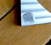
I did a quick experiment yesterday, to see if epoxy sticks to this Ti. very well, and it didn't this time anyway. It was fairly
easy to pry off some of it with a knife tip. To be fair though, I just cleaned the milled surface well with solvent, and used
some generic 5 minute epoxy, which isn't the best, just for a quick test. (OK, it was a minimal experiment)

IMG_2478 (1) copy.jpg

We painted Titanium bikes at Trek back when they were in vogue, and had to use a special primer on them because epoxy
and urethane primers wouldn't stick well enough.

I'll give it a better try,.. sand or sandblast the surface, and use a better quality epoxy. I'll try heating it up too, after it's
dry, I imagine not all epoxies act the same.

Theres also red Loktite, or just soak everything down with motor enamel.
 
APL said:
I did a quick experiment yesterday, to see if epoxy sticks to this Ti. very well, and it didn't this time anyway.
Yeah, epoxy does not adhere to bare Ti well at all.

I would suggest (at the bare minimum) you grit blast to clean off Ti oxide layer and increase surface area/roughness.

In addition to that you could use a surface prep such as 3M AC-130-2.

Remember, adhesive bonding is optimal for loading in shear, and sub-optimal for loading in tension or peel. So if there are any tensile or peel type loads, consider additional methods of fixing.
 
Thanks serious_sam, I had to wonder if trying to peel it off was a very good test or not. I'm not really using it that
way anyway. It would probably act the same on unprepared aluminum. I need to do a better test for sure.
But I've suspected that Ti. was a little more difficult to bond to than most.
 
I was able to drill all the holes for the pins, and didn't have any trouble this time,.. getting all 18 done with one bit.
Using the mill, lower rpm, and applying enough feed and pressure to get one good curl coming out of the hole seems
to do the trick. Now it's just a matter of cutting and sand blasting the slots, and bonding in the ceramic beads :wink:
 
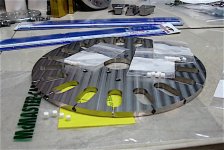
That all went well,.. the Ti was surprisingly easy to cut with the hacksaw, and the holes are a perfect press fit.
Just need to epoxy the cuts, and round off the edge, and I think she's ready to go. :)

Slots cut and drilled.jpg

I'm getting good vibes from it. The pins may look a little wimpy, but they're tight and right, so it's not going to move.
(Coleasterlings titanium stator plate has to qualify as true motor-porn.) 8)
 
Looks great, sir! How'd you end up holding it for drilling and how'd you index it? Cobalt drills?

It saws surprisingly well. We cut A LOT of 3" bar back in the day with a chinese, controlled feed horizontal saw with lenox blades. Then we switched to a fully-automatic Hydmech with a carbide blade and promptly destroyed all the teeth. Went back to bimetal and never had another issue, haha.
 
I used a slotted cast iron right angle block on the mill table, and turned an aluminum center holder, so I could mount
and rotate it vertically. Marked and pre-punched the holes, set the center line with the handle, and then eyeballed
the rest. Held my breath a lot.

I wound up buying some generic cobalt .166" OD drills from McMaster, thinking that the hole is always going to be a
little larger than the drill bit, and the fingers would move another few thousand's for a tight fit. The pins are .170"
So far so good, but it's the last pin that will be the hard one.

For the cuts, I clamped a piece of flat stock to the plate for the hacksaw blade to follow down, for a nice straight cut.

Dang air compressor blew the start up capacitors again, (I think), so I have to haul in the little backup unit from the other
shop just to blast the cuts. Sometimes getting through the day is like pulling teeth around here.
 
Looking very nice. If the last pin is too tight, you might try cooling the edge of the disk with dry ice to make it shrink a little.
 
APL said:
I used a slotted cast iron right angle block on the mill table, and turned an aluminum center holder, so I could mount
and rotate it vertically. Marked and pre-punched the holes, set the center line with the handle, and then eyeballed
the rest. Held my breath a lot.

I wound up buying some generic cobalt .166" OD drills from McMaster, thinking that the hole is always going to be a
little larger than the drill bit, and the fingers would move another few thousand's for a tight fit. The pins are .170"
So far so good, but it's the last pin that will be the hard one.

For the cuts, I clamped a piece of flat stock to the plate for the hacksaw blade to follow down, for a nice straight cut.

Dang air compressor blew the start up capacitors again, (I think), so I have to haul in the little backup unit from the other
shop just to blast the cuts. Sometimes getting through the day is like pulling teeth around here.


Awesome, great job! I was going to set it up on the 4th axis with a custom arbor that held it off of the chuck far enough to be able to get a slitting saw in there from the side. The 4th has a big enough chuck that it would have interfered with the saw and I didn't want to slit my chuck too, haha. Keep it up!
 
serious_sam said:
Remember, adhesive bonding is optimal for loading in shear, and sub-optimal for loading in tension or peel. So if there are any tensile or peel type loads, consider additional methods of fixing.

As it looks, the two halves from the cores are held together with the countersunk screw so the glue would be mainly have the purpose of filling the gaps and keep everything in place.

APL said:
That all went well,.. the Ti was surprisingly easy to cut with the hacksaw, and the holes are a perfect press fit.
Just need to epoxy the cuts, and round off the edge, and I think she's ready to go. :)

Awesome :thumb: , looking forward to see how it performs and which values you get for kV and R.
Do you have FOC controller, or which one you going to use?
 
I'm using a 50 amp HPC rebranded Crystalyte controller at the moment. The battery setup isn't much to write home
about, so upgrades are in order. At best, I'll just be able to put 500 watts through the motor, once she gets
spinning for the road test.

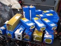
But I was graced with a donation of lithium packs last year,.. with cheap BMS units that malfunctioned, from a local
scooter importer. Lucky me, when it rains, it pours. Some bigger and better BMS's, and hopefully I can get at least
some use out of them.

Batteries!!!.jpg

So I have some firepower, and just need to reconfigure the bike so that I can use them, which is what the new frame is
all about. The most I can do now is bench test the motor with them, but I plan on using two of the 13s packs for 52v at
abut 70 amps in the new bike. Should be good for a few thousand watts, and able to push a motor pretty hard.

I haven't even cracked the door open on the world of controllers yet, since I haven't really needed to yet, and have my
hands full building a motor,.. I'll need your help and expertise as to which controller is more suitable. :thumb:
 
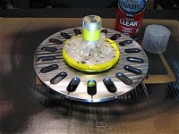
Pins are bonded in, and the cuts were blasted and filled with epoxy. Edge is rounded, and I sprayed a coat of clear
enamel on it, just to get a little more insulation for the wires and cores. I'll spray a light coat on the bottom of the
cores too. Certainly seems rock solid!

Stator cleared..jpg

I shattered a few of the pins pounding them in,.. ceramic is tough, but it don't like being beat on much. So I ordered
a few more of them, and should be able to finish it up in a few days. Other than that, I think I'm ready to put it all
back together again at long last. :)
 
This is like waiting for Christmas presents as a kid. Gotta check the forum like 3 times a day for an update, haha. Good stuff!
 
I'd like to move faster but theres lots of little things that are slowing progress down, Locktighting all the core screws,
and rearranging the coil wires,.. plus, I forgot to file the phase wire clearance in the new plate, are a few.
I didn't drill any 'through holes' in the plate for wires to go through this time, so it's not quite a direct transfer, and
I have to get creative with the coil wires.

I also want to mill a millimeter or two off of the rotor spacers, to try and get a smaller air gap this time, and that will
mean re-shimming the bearings to get a centered stator,.. always a labor intensive job, and no easy way to do it. But
I think that the 'centered stator' is the key to getting these things to work, and the 2+mm air gaps that I had last time
made for a really soggy torque.

Well, slow and steady wins the race, I'll have some pictures and a better progress report soon. I know,.. I'm excited to
find out how this new plate will turn out too! :)
 
Looks like it's not going to go easy,.. the coil crossover wire is tight and I'm getting shorts. So I guess I'll have to rewind
half of the cores to get some slack, and add some shrink tube. My fault for adding some diameter to the slot cuts.

The clear enamel I sprayed on it didn't stick well enough to even use, so I stripped it off and used some Kapton tape to
insulate the plate/coils. (I should have just printed some coil bobbins from the start)

V2 coil crossover..jpg

I'm running two coil wires over the top, instead of going through the plate this time,.. 18 more holes will just make it
weaker, short out easily, and it's easier to take apart this way.

There's the idea of wiring each side independent, and then just tying the phase wires together, only running three wires
through the plate. Which is tempting,.. but the big washer is taking up all the space on one side, so there isn't very
much space for coil wires, or phase wires.

Good news is, the cores fit the plate super perfect, and they are solid as a rock! Coleasterling nailed it,.. I can't feel
any play in them! :thumb:
 
APL said:
the coil crossover wire is tight and I'm getting shorts.
Too tight to use Kapton tape between the wires and the plate edge/corner?
 
Back
Top