APL's DIY axial-flux motor

Thanks for the kudos,.. couldn't have done it without all the help and ideas from all of you!
And I'd like to give a special thanks to Coleasterling for all the help he has devoted to the cause! :thumb:
Definitely couldn't have got here without that.

She's made it over quite a few humps all right, but it will be interesting to see what this stator can take. Hope she
gets over the 500w mark, and in to the thousands!

I'll run it as-is for a road test, but I'd like to get a narrower gap down the road. One reason is, I don't feel that much
cogging when I turn it by hand. Not as much as I would expect anyway, with so much steel and magnets.
Unless I'm missing something,.. might it be inherent of a 18S/20P ? Narrow slots? SMC?

I checked the back iron for flux leakage, and while a steel wire will stick to it a little, it isn't very much. I may have
to add some steel rings to the outside rotors yet, when the power goes up, but for now it seems good.
 
A smaller gap will increase iron losses so if you get enough torque, you may want to stay with the larger gap.

I'll be interested to see what you get for a no-load power input once you get the CA calibrated.
 
Thats another reason,.. the torque. Last time I road it, the throttle was a little soggy, and I attributed it to the gap.
So I hope thats it or I have bigger problems. I hope this SMC isn't going to let us down. :|

I took the no load test reading today, and noticed that it picked up speed, at 40v / 800 rpm. The last time it was
40.8v at 730 rpm. (Near as I can tell, it's drawing 20 watts.)

I ran the phase wire outputs too, and confirmed a higher Kv. New = 15.4v at 520 rpm. Old = 18v at 439 rpm.
So it's now 25 Kv, and it was 18 Kv,

Not too surprising since I had too take several half turns off the coils in order to get them to fit, and conform to the
new set up. I guess I'm not sure how air gap affects Kv.

Either way, she's running a little faster now, but not too much. So it still comes down to how much torque, and how
much current or heat generated to get it. Need to do a ride test.

Good news is, Amberwolf was right on,.. It was a 4 pin connector on the CA shunt wires that was craping out. I'm going
to take it out and direct solder. :thumb: Bad news is, the cheap RPM laser meter died today, so I have to order a new
one.
 
20w is very low for a motor that big. It represents mostly the iron and windage losses. A very good sign there. My old BMC motor took like 250w running no load (admittedly at about 2x the rated RPM).

If you can pump in enough amps, you should get some torque. Reducing the gap will slow it down but give more torque.
 
Good to hear that 20w is low, I didn't write down what it drew for watts with the fiberglass stator. I'll have to go back
in the thread and see if I can figure out how to calculate motor efficiency, and if I have enough test info to do it.

I'd like to do the road test, but the weather is not cooperating,.. single digits with snow and ice packed roads make it
a bit dangerous. Not worth a cracked hip, or broken arm.

Looks like this Polar Vortex is going to stay put for a while, and I can't think of any indoor places to ride that will work,
so I guess it's time to dig out the turbo-trainer, and see if I can get it to work out. It's too bad, since normally all I would
need to do is roll down the driveway and ride. :roll:

I only need about 500w of resistance, (for this battery pack), so maybe between the rear brake and the trainer it will work.
 
Yeah, as fetcher says, don't be shy on the Amps you give this motor.
It looks beefy as hell, I'm sure it can takes thousands and thousands of watts no problem.
 
You could use the rear brake for a quick test. The brake will overheat pretty fast at full load.

Time to make some studded snow tires... :wink:
 
Yep, the 500 watts is just to check the stator flex, and I can do that indoors, but the motors performance is best done
on the road. If this first test works out, then I plane to jump right in and build a bigger battery case so I can pump
more and more amps into it. That will be the fun part,.. :)

I was looking for info on motor efficiency on the "Things in Motion" site, and found a lot of good info on no-load speed,
BLDC/PMSM wave forms, and FOC vs Standard controllers. (Love that blog)

No load speed is the point at which the coils or are producing the same voltage as the battery. So at 800 rpm, the coils
are producing 40v. As Fechter stated earlier, the watt draw represents the combined inefficiencies of the iron, copper,
air and bearing resistance, etc. The iron usually having the biggest contribution.
A perfect motor would have no watt draw at no-load speed. (In a perfect world)

The wave form produced from the phase wires can be square or rounded, which determines the controller type likely
needed. I have a crappy oscilloscope somewhere that I'm going to try to dig out today, and see if I can get a reading
from it. It would be nice to see the wave form this motor has,.. as the right controller can make a big difference in
performance.

Anyway, most of you probably know all this already, so sorry to ramble on,.. but heres the page for reference. (Upper
portion)
Things in motion: https://things-in-motion.blogspot.com/search?q=efficiency
 
The oscilloscope turned out to be a bust, so I'm going to keep an eye out for another one on Craigslist and the Bay.
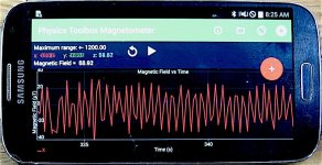
I had a thought that maybe I could get a waveform on the smart phone magnetometer if I connect a coil to the
phase wires, and put the phone next to it.

It works, but not like an oscilloscope. I can get a reading of the entire rotor revolution, which is interesting, but the
information is not very useful at this point, other than the highs and lows are relatively even. The reading also
reflects the drills output, that I have spinning the motor. So unless the motor can be turned perfectly smooth,
the information will be compromised somewhat.

IMG_2541 (1) copy.jpg

There is another Ap called the "Physics Toolbox Sensor Suite Pro" that I plan to download, that has several useful
instruments that you can use, including an oscilloscope, but the scope is audio driven.

Physics Toolbox Sensor Suite Pro; https://play.google.com/store/apps/details?id=net.vieyrasoftware.physicstoolboxsuitepro&hl=en

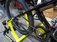
On the good side, I was able to get the trainer set up, and the motor back in, and it looks like it's going to work really
good,.. plenty of resistance in the hight gears, even without using the brake. Batteries are all charged, and if all goes
well today I'll have some specs tonight, and a verdict on the stator plate strength. :)
 
APL said:
The oscilloscope turned out to be a bust
Which scope is it? Might be easy enough to fix.


There is another Ap called the "Physics Toolbox Sensor Suite Pro" that I plan to download, that has several useful
instruments that you can use, including an oscilloscope, but the scope is audio driven.
I haven't tested the scope yet, but the other stuff in the basic version of that app has been useful. Unfortunately my relatively ancient devices don't have all the sensors needed to use a number of things it can do. :/

Audio scopes are limited to the frequency range that the input circuitry filters to, and the converter sample rates. So that's usually somewhere around 100-200hz up to 15-20khz. That's probably just fine for the motor speeds you're after. Spin the motor at say 100rpm, times however many magnets, is still only in the low khz range, probably ideal for the audio scope inputs.

To use the scope you'd need to make a circuit that divides the voltage from the motor and limits it (zener/resistor?) to prevent it from ever exceeding what the audio input on your device can actually handle (this is usually a very small voltage). There are a number of makers of buffer devices that are intended to be used with any of these audio scopes, including those for desktop-pc soundcards if you want something fancy, or you can make your own very simple one (with no protections) like this:
https://www.nutsvolts.com/magazine/article/turn-your-computers-sound-card-into-a-scope
NV_0419_Bogatin_Figure09.jpg


Or a more complicated but "safer" buffer circuit like this, that will affect the incoming signal less as well:
https://www.analog.com/en/analog-dialogue/articles/turning-pc-sound-card-into-sampling-oscilloscope.html
soundcard-fig-01.jpg


Or somethign in between that allows for some adjustment of input level, etc:
https://makezine.com/projects/sound-card-oscilloscope/
herocrop.jpg
 
Thanks amberwolf, thats all great information! The scope I have is an automotive unit, made for ignition testing.
It was a DIY "kit" that my father assembled back in the 70's, and simply doesn't have the inputs or controls needed.
I thought all scopes would at least be able to show a wave form,.. but not this one. I thought about hacking into it,
but used scopes are pretty cheap if one is willing to wait and do the searches. ($50 - $100.)

The Physics Toolbox one uses the phones mic., so I would need to convert to an audio signal cause I don't think I
can do a direct connect. :?:
Plus, I think it needs to have a sweep mode, in order to single out one or more waves. Although, you could freeze
the image, and expand it on the touch screen.

I have limited experience with oscilloscopes, mostly as a youngster, and don't remember how they work too much
anymore, so it would be nice to have the old CRT version around to play with anyway. I think that's what I'm going to
need to get the image I'm after,.. and you gotta love that green screen! :)
 
Well, I did the motor/trainer test today, and I'm afraid that it was a little disappointing. I was able to put 400 watts
to it without rubbing, but only if I held it steady. If I throttled it very fast, it would rub. Still,.. better than it was.

V2 Stator test 2.0.jpg

The motor is usable, and I still look forward to a road test,.. 400w was all the bike ever used before anyway, but
still far short of our goals. (Keep in mind that the mid drive has a 3 to 1 reduction, so 400w equates to 1200w at
the rear axle.)

The throttle is still soggy too. One thing I noticed, is that when I short out all the phase wires to each other on V2,
the motor becomes hard to turn, (of course), but when I do the same on the Crystallite, it's 2 to 3 times harder to
turn. Indicating a much weaker magnetic circuit on V2.

This could come from the SMC's inherent magnetic ability's, or the PM magnets strength, or the back irons ability to
move flux, or the fact that I'm using the slots to move the circuit through the stator plate, and it's being restricted.

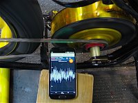
I thought that if the back iron is leaking, then it should show up on the magnetometer when I put a load on it, but
after doing so, I saw no such thing. The graphs AC signal strength remained fairly straight, and centered on the screen.

IMG_2556 copy.jpg

So whats the bottom line? I guess I'll wait for the weather to clear up, and do a road test first. Then take it apart and
see where it's actually rubbing inside. Then I'll see if I can turn the PM's and get the air gap smaller and more even.

After that, I don't know. It may also be that the rotors are whats rubbing, from being able to cave in a bit, two
piece rotors aren't the best idea, and they are too thin to start with. I'll try to figure out a way to test for that,
maybe with a laser measuring tool aimed at the side plates. I still think that the stator plate is plenty strong enough.

The hard part is determining whether or not the SMC is not up for the task, or if the design is flawed with the
restrictive magnetic path through the stator plate. I don't have any way to figure that out yet.

Either way, V2 appears to be headed for the shelf as another successful failure, much like V1, and it looking like
were going to have to come up with a better design, and most likely go back to the dreaded laminations.

I'm definitely up for V3, but I have to get my new bike frame built first, and that will give us plenty of time to kick
some ideas around.
 
APL said:
(Keep in mind that the mid drive has a 3 to 1 reduction, so 400w equates to 1200w at the rear axle.)
Unfortunately, power is still power, so you only get at most the same watts at the wheel that you started with at the motor...less actually because the reduction isn't 100% efficient.

You get more *torque* at the rear wheel by converting it from the *speed* of the motor thru the reduction, however. :)
 
APL said:
The Physics Toolbox one uses the phones mic., so I would need to convert to an audio signal cause I don't think I
can do a direct connect. :?:
The phone probably has a mic input on the headphone jack, if you use a TRRS (vs TRS) plug.
https://blog.zzounds.com/2020/05/29/ts-vs-trs-vs-trrs-cables/
The simplest way to make the adapter is to buy a cable like this
https://www.amazon.com/3-5MM-Right-Stereo-Silver-Plating-Copper/dp/B0793JNYLL
(there are much cheaper ones; this was just the first hit on google)
and cut it in half (or near the end you don't want to use if you only need one, and want the longest wire), the splice the cut end into whatever frontend you use to attenuate/isolate the test signal from the phone.

Or adafruit has this nifty bit
https://www.adafruit.com/product/2914

If you buy a premade frontend it'll probably already have the TRRS cable to plug into your headphone jack. If it only has a TRS plug you can use a TRS to TRRS adapter, which are pretty common too.

I went ahead and ordered this cable (cuz the 10foot is cheaper than shorter ones, and I can use the extra wire for something else), to try out with my device running the PTS app:
https://www.amazon.com/dp/B01MUCPB8O/ref=dp_iou_view_product?ie=UTF8&psc=1


Plus, I think it needs to have a sweep mode, in order to single out one or more waves. Although, you could freeze
the image, and expand it on the touch screen.
Most likely you won't need to worry about that--the software will liekly auto-lock onto the waveform to display it on screen, so you don't have to fiddle with the scaling or with timing of the input like you would an analog scope to lock it to a stable viewable waveform (like I do now with my tiny Hitachi scope, or used to have to do with my ancient St-Bernard-sized 1950s roundscreen HP scope). My current test bench setup:
https://endless-sphere.com/forums/viewtopic.php?f=30&t=105711&p=1551378&hilit=hitachi#p1551378
file.php

with the scope in the corner on top of the giant Sorenson PSU, and a closer pic of the scope
file.php


one of the ancient HP scopes I used in this thread
https://endless-sphere.com/forums/viewtopic.php?f=30&t=32838&p=501665&hilit=hitachi#p501037
file.php

with a scale pic of the little Hitachi with the same psu and motor next to it
file.php


I've considered a few times of getting one of the cheap sub $100 digital scopes just for portability...but 99.999999% of times I actually need to use a scope it's easily within audio frequencies, and would work with a phone app thru the headphone jack with one of the devices you can make that I linked to and showed in my previous post, or one of the many you can buy premade.

There's also DIY kits like this random example
https://www.amazon.com/Roeam-DSO138mini-Oscilloscope-0-200KHz-Pre-soldered/dp/B07RYT2TCY
(cheap enough to integrate into my "wierd dashboard"...see later in the post)


There are even frontend units you can buy that then send the data over bluetooth or thru the USB OTG on the phone, to a specific scope app they come with, but I'd just use my little old Hitachi. :)
Random example:
https://www.amazon.com/Oscilloscope-OSC482M-Channels-Bandwidth-Resolution/dp/B07TB8V2X1
or this
https://www.amazon.com/EspoTek-Labrador-Easy-Use-All/dp/B07CVB7ZJG

I have limited experience with oscilloscopes, mostly as a youngster, and don't remember how they work too much
anymore,
Thankfully, there are lots of guides out there. ;)
https://www.google.com/search?q=how+to+use+an+oscilloscope


so it would be nice to have the old CRT version around to play with anyway. I think that's what I'm going to
need to get the image I'm after,.. and you gotta love that green screen! :)
Yes...I happen to love knobs and dials and analog gauges and whatnot, and if it were practical and possible, I would have all sorts of this gadgetry on the trike's "dashboard", including some Nixie tube displays for digital readouts, and the like. :oops: I've drawn up a few dashboards like that for it and previous bikes, but never have been able to spend the time (and money) on developing and building them out for real.
 
Wow, that all sounds great! I didn't know about the smart phone having a TRRS jack,.. shows how much I know about
those things. It all makes sense now, and sounds like a good, (and cheap), way to go. :thumb:

I'll get the new Ap downloaded, order up a cable or two, and see how all that works out. Thanks for all the great links
and info. The smart phone is definitely more user friendly and portable than the big scopes, plus theres all the other
tools in the PTS box.

I'm still going to keep an eye out for an analog scope too, because they have tons of other features, and look so cool in
the shop. :wink: I like your little Hitachi by the way,.. looks like the perfect bench scope.

My Dad had one of those all tube round screen monsters, with more knobs and buttons than you could count, took two
people to carry, and a few minutes just to warm up. :lol:
I saw the super cheap little digital units and kits on the Bay, but decided that the money is probably best spent on a used
analog scope for the shop, (could be wrong about that though.) I'll check out the phone set up first.

Nixie tube displays,.. thats funny! My, my, how far we've come, tubes to transistors to chips, and now smart phones and
TV's,... wonder where we'll be in another 50 years?
 
Implants and bionics. Or not even implants, just grown right inside from an injection or pill that "tells" your body what functions you want to add and where. :lol:
 
Sounds about right, ,.. I'm sure that the humanoid robots are coming too, so either we'll be hacking them, here on the
ES,.. or they'll be hacking us. :confused:
 
APL said:
Well, I did the motor/trainer test today, and I'm afraid that it was a little disappointing. I was able to put 400 watts
to it without rubbing, but only if I held it steady. If I throttled it very fast, it would rub. Still,.. better than it was.

The motor is usable, and I still look forward to a road test,.. 400w was all the bike ever used before anyway, but
still far short of our goals. (Keep in mind that the mid drive has a 3 to 1 reduction, so 400w equates to 1200w at
the rear axle.)

The throttle is still soggy too. One thing I noticed, is that when I short out all the phase wires to each other on V2,
the motor becomes hard to turn, (of course), but when I do the same on the Crystallite, it's 2 to 3 times harder to
turn. Indicating a much weaker magnetic circuit on V2.

This could come from the SMC's inherent magnetic ability's, or the PM magnets strength, or the back irons ability to
move flux, or the fact that I'm using the slots to move the circuit through the stator plate, and it's being restricted.

I thought that if the back iron is leaking, then it should show up on the magnetometer when I put a load on it, but
after doing so, I saw no such thing. The graphs AC signal strength remained fairly straight, and centered on the screen.

So whats the bottom line? I guess I'll wait for the weather to clear up, and do a road test first. Then take it apart and
see where it's actually rubbing inside. Then I'll see if I can turn the PM's and get the air gap smaller and more even.

After that, I don't know. It may also be that the rotors are whats rubbing, from being able to cave in a bit, two
piece rotors aren't the best idea, and they are too thin to start with. I'll try to figure out a way to test for that,
maybe with a laser measuring tool aimed at the side plates. I still think that the stator plate is plenty strong enough.

The hard part is determining whether or not the SMC is not up for the task, or if the design is flawed with the
restrictive magnetic path through the stator plate. I don't have any way to figure that out yet.

Is there any way to see through the slots to see where it's rubbing without taking it all apart? I guess it's possible the rotors are flexing now that the stator is beefed up.

I don't think machining the magnets to even them out is going to be easy. Most processes will destroy the magnets. Steel shims would be better.

The shorted phase wire/turning resistance test is a good one. That will give a good indication of the torque potential. A smaller gap would improve things there. With as much force as it takes to remove the rotor it seems like the core material is permeable enough but hard to compare to steel without actually trying.

I think your back iron is good enough based on your test.
 
With the trainer set up I can look closely at the motor rotors and gaps when it rubbing, but try as I may, I can't actually
see any movement. It's going to take some kind of instrument to detect the small amount that it's moving, and where.

If it's rotor 'sag' then it will be difficult to detect, other than beefing up the rotors, and trying it out.

Perhaps a laser measuring tape,.. I don't know how sensitive they are, or I thought maybe a magnet placed on the rotor
in various places may give a magnetometer reading change. If I put something reflective on the rotor face, I might be
able to reflect a laser pointer beam off of it, and see a change on a piece of paper some distance away. :?:

Another possibility is to allow something like a stick or rod to rub on the rotor side, and then put the dial indicators
somewhere on that, but the "shake" may be too much for it.

I should have sprayed some machinist dye on the core faces before I put it together, which would show the rub points,
but I'll have to do that next time. It should be somewhat visible when I take it apart anyway.

So, it comes down to the rotors, the bearings, or the stator again. But even if that issue is cured, the low magnetic circuit
may be the death null for this project anyways. It's hard to get around that point. It may be that SMC is only good enough
for fan motors and lower power devices, and not able to deliver the big power we want. (the info we were after anyway)

The amount of SMC material that is not able to pass magnetics through the slot doesn't seem like that much, so I have
to question that thinking too. I'm trying to figure out an experiment for that. (I have a few extra cores)

Getting spanked again, yep,.. that's two for two, I'll keep trying. This is the stuff that makes old men wise. :)
 
With all motor designs there are trade-offs. The SMC stuff seems to be very low loss, but apparently at the expense of torque density. Another test is to try to measure the flux density in the gap. I have a super thin hall effect magnetometer made for this at work. Pretty expensive.

A cruder way would be to measure the pull of the magnet against a core and maybe compare that to a piece of steel. This could be done with just a spare core piece and a magnet on a piece of back iron. Once I made a pull force measuring setup using a digital scale. I stuck one magnet to a weight that was heavier than the pull needed to let go. The other magnet was stuck to a big piece of aluminum bar bridged across the scale on some wood supports. With no pull, I measured the weight, then slowly pulled on the top magnet until it let go and tried to see what the minimum weight was. A digital fish scale with a hook is also nice if you have one.
For a given magnet size, the pull will be proportional to the flux density.
 
I can try that,.. if I machine a piece of steel and a piece of SMC to the same size, and epoxy them to opposite sides of a
thick aluminum bar, then all I have to do is flip the bar over to get the two readings. The steel will be the 100% reading,
and the SMC will be a percentage of that. Distance from the magnet shouldn't matter too much.

Probably should have done that in the beginning, but I was to starry eyed and hopeful that SMC was the answer to the
lamination woes. The cores were left a little oversize to help make up for the lesser steel content.

At any rate, it's an easy experiment and may help to confirm or deny what were seeing in the motor. :?:

The weather is getting better around here, and I can get back into the shop again to try some things out, and by next week
I can get a road test done, and start tearing the motor apart again.
 
Distance from the magnet is important. Comparing at long distance will tell us something also and that's easier, but what you really want is a measurement at the same distance it is in the motor, like 1mm. If the permeability of the core isn't enough, a lot of flux will fringe and go back to the magnet without going through the core. The amount of pull you get at motor gap distance will be about directly proportional to the torque you would get for a given number of amp-turns on the winding.

You're right we should have tried this earlier, but based on the specifications for the material, it seemed like it should be good.

One other thing that might help is more turns, especially if your controller is low on amps. Not a fun project either. I don't remember if you connected delta or wye. A wye connection will give you a little more torque per amp.

But the rubbing problem is the killer. I can't think of a good way to measure the deflection when it's running. Only thought I had was to make a pair of wire "feelers" you place so the tips are almost touching the rotor. Like a wheel truing setup. When it starts rubbing you can maybe see if one of the feelers is also touching.

If the rotor turns out to be too flexy, you might get away with only beefing up one side.
 
Hmm.. measuring the gap is not so easy, I see what you mean about the fish scale, as the pull is opposite of the bench
scale. I've been giving it a lot of thought though, and I think I found a way, using the motor's rotor and a spare core.
Probably a good idea to use the actual motor magnet and core to get a close reading.

It will only be one side though, at first, unless I can figure out how to do both sides at once. ( I could just use a 1mm
spacer on the second core gap.)

That should tell us something. With all the steel and magnets this thing has, it should be much more capable than what
I'm seeing so far. If I can get the gaps a little tighter, and balanced, it may come around a lot more.

I was thinking that it needs more windings also,.. if it's not able to operate in the rpm range it was intended for, the
performance will always be compromised. Some smaller gauge wire with more winds will be the next step, once the rub
can be figured out.

It's at 800 rpm no load now, so with more turns and a smaller gap, it should get closer to the 500 rpm target speed.

If it comes down to the rotors, I can add another all steel one to the outsides, replacing the aluminum part, making
the rotors twice as thick, and more or less one piece steel. (1/4" thick)

Looks like a good day is coming up, with warm weather and clear roads, so if I can get a short ride in, I'll start the tare
down, and see what we can see & do some test to try and get to the bottom of this.

The motors usability is not so important at this point, par for the course and motors I can always make, but the SMC's
usability is important, and we should at least try to determine that with this build.
 
I was able to get out for a short road test and the results are pretty much the same as they were last time, with the motor
drawing about 300 - 400 watts before it starts to rub. It draws around 250w at 25 mph.

I get the feeling that even though the stator is several times stronger, nothing has changed, and the problem is probably
elsewhere in the motor. Time to give more thought to the rotors and bearings,.. I'll take the motor apart today, and see
what can be seen.

My newest idea to 'temporally' save time and move forward with the experiment is to place something in the gaps that will
keep the stator centered. The material of choice would be Teflon PTFE sheet, which has a friction coefficient of .05 and is
the third most slippery material known to man, often used to make bearings.

Definitely a 'cheat', but it will allow me to pump more amps into the motor while I search for the real problem, and if it
works then it was worth the try,.. and nothing lost in trying. I can get .031" sheet, which will allow me to get down to an
.035" gap which is about .8mm.

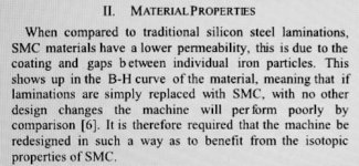
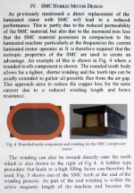
Other than that I've been researching SMC again, trying to find information relevant to air gaps for the material. I came
across this page and realized that I'm going the wrong direction in trying to make SMC to run slower and get more torque.
We already knew that, but evidently it takes a while for things to sink in for me.

SMC only has an advantage in the high speed - high frequency range, and laminations in the low speed low frequency
range. So I'm thinking I'll need to go with a chain ring size cog in the back, and a higher voltage battery in order to even
get closer to what the motor should be seeing for rpm's. Usually in the 2000 rpm range.

IMG_2578 (1) copy.jpg
IMG_2579 (2) copy.jpg

Taken from Researchgate;https://www.researchgate.net/publication/297403555_Application_of_the_latest_Soft_Magnetic_Composites_to_a_Hybrid_Brushless_DC_Motor_for_a_Compressor_Application

The page also suggest that the cores have more rounded ends for SMC than laminations, which was suggested earlier in
this thread, but of course in all my un-wisdom I went with more traditional. :confused:
 
Back
Top