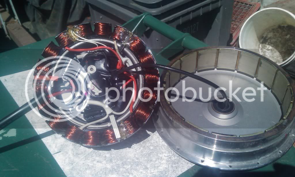
Definitive Tests on the Heating and Cooling of Hub Motors

justin_le said:
I have not tried or experimented with this yet, and given all the small muffin fan failures that I've had to deal with over the years from failed computer power supplies and battery chargers, I'm pretty disinclined to want a stash of them inside my hub motor. Those things are delicate and not meant for abuse. But I also have no doubt that independently powered fans like this will work better than anything else as a cooling strategy at very low speeds...

I don't blame you at all. Muffin fans aren't the way to go. Not only are they failure prone, but the flow rate of axial fans is too easily disturbed. Small centrifugal fans are better a fighting flow restrictions, plus their output is at a 90° angle to the intake so their more focused flow can be directed at the stator where it is needed, and they're better at pulling a pressure.
 
liveforphysics said:
~1min to achieve a internal thermistor reading of 1.3kOhm before FF.
>5min (more like 10min) to achieve 1.6kOhm (indicating lower temp) internal thermistor reading after adding FF.
That's pretty impressive effect for a few ml of anything.

I know isn't that the most amazing thing? It seems like the most inconsequential addition of stuff to put in these giant motors and then presto, you've doubled the ability of the motor to shed heat from the windings.

Anyways, we're now priming ready to get this in the hands of enthusiasts for wider scale distribution and field testing, and take it out of the lab on into people's bikes.
Bulk Supply.jpg
Packaged in capped 10mL plastic tip syringes you you can just drill a small hole, squirt, and be good.
Syringe of FF.jpg

The thing we gotta do next is packaging and branding and coming up with a memorable name for the stuff. After some fun brainstorming sessions we settled on the two frontrunners of:
  • Ferroids and
  • Statoraid (or Statorade)
Ferroids works great with the whole injecting a small syringe of stuff in the motor to boost performance, but I worry that it gives the impression that it would lead to an immediate increase in power from the motor which isn't true, you'd need to up the current limit of the motor controller for that. Statoraid doesn't have the same visual imagery, but it holds true because because it's alludes to the long duration endurance side of working out, when you need a hit of refreshing electrolyte drink to keep the body going, only now this help keeps the stator going.

What do you guys think!?? A few others that came close were
Coiloil, motordoper, statachilla, ferrochill...
 
Must say I like coiloil and ferrochill the best, and my vote would go to ferrochill. Is to say, people would the remember the phrase Ferrochill, and to top it all the name is self explanatory.

I can just picture heaps of trouble if a syringe get caught on scanners when they cross the borders. Then the custom reads on the package label the package contain a syringe filled with
12 ml of Ferroids. CAusing all kinds of bells and whistles to light up.

That package wouldn't be delivered in the mail box any day soon......
 
I vote for Ferrochill or Ferrocool...(leaning towards Ferrocool). If you go with Ferrocool, in exchange...you must agree to be seen in public wearing an ElectricBike.com T-shirt that I will provide for free (PM whether you like dark green, dark blue, or black). PS, I still have the Cycle Analyst that you autographed, and no...it's not for sale.
 
Statorade!

I will definitely look at epoxying + FFing my QS 205. Is there any consensus on the best compounds for potting stators and rotors for both protection and heat transfer?
 
Wow this thread moves fast.
markz said:
What kind of CFM or those fans?
I saw some fans in an electronics store and I thought about your mod. Are you gunna cut open the side plates? or just have the fans enclosed?
These little fans are 5.13CFM each at nominal 7.2V, which is a lot for a 25mm fan.
http://www.yeahracing.com/catalog/y...gh-speed-ball-bearing-25mm-htn304-p-3471.html
If you were gonna do it I wouldn't buy normal PC fans as they cost the same and push less air than these.
The side covers will be drilled again. The idea is to suck fresh air in one side and push it out the other. This isn't the first time I've done this, and it's proven itself to work already.

justin_le said:
I have not tried or experimented with this yet, and given all the small muffin fan failures that I've had to deal with over the years from failed computer power supplies and battery chargers, I'm pretty disinclined to want a stash of them inside my hub motor. Those things are delicate and not meant for abuse.
They might not be meant for abuse, but that doesn't mean they can't take it. I rode through a flooded creak with them running and they were fine.

justin_le said:
But I also have no doubt that independently powered fans like this will work better than anything else as a cooling strategy at very low speeds. So I think what you and cowardlyduck are doing is awesome and quite viable for a modder/hot-rodder, but I'd hate to go there on a commercial product. There's gonna be a certain vehicle speed where the effects of external moving air flow would start to dominate and become more significant than what the inside fans are contributing, and it would be interesting to find at what point that is. 10kph? 20kph? 30kph? It wouldn't be too hard to test, but when/if I do pursue more experiments with vented side covers the focus will be on passive techniques of directing external passing air flow through the hub, rather than using an active approach. In the past when I have held up an anemometer behind those types of fans I've been pretty surprised at how low the actual air velocity is that they expel, on the order of 10kph or less.
Thanks for the acknowledgement Justin. :)
Yeah I can see why it would be a hard sell to turn this approach commercial, although there are plenty of actively cooled electric car controllers and even motor's out there with nothing more than standard fans doing the job. I'm sure it could become a valid pursuit for a commercial product if the engineering behind it was done first to eliminate fan failures and limit particulate ingress. Heck fans work perfectly fine already in regular cars/motor bikes as radiator coolers and handle all sorts of abuse, so surely they can't be that bad.

John in CR said:
I don't blame you at all. Muffin fans aren't the way to go. Not only are they failure prone, but the flow rate of axial fans is too easily disturbed. Small centrifugal fans are better a fighting flow restrictions, plus their output is at a 90° angle to the intake so their more focused flow can be directed at the stator where it is needed, and they're better at pulling a pressure.
I agree with you John, however the challenge lies in mounting and making centrifugal fans fit the standard stamped steel stator support of most hub motor's. The great thing about the 25x25mm fans is they are the perfect fit for the existing holes in these motors. If you know of a centrifugal fan that would fit these motors well, I would be keen to give them a try.

I vote for Statoraid. I didn't realise you were attempting to make this into a commercial product Justin. That's great if you are.

Cheers
 
Justin is looking like a big time drug dealer in that picture.

A bit more research on the formulation of ferrofluid indicates most of the common ones use kerosene as a base. If it's run-of-the-mill kerosene, it should be evident by the smell. There are also synthetic versions of the kerosene which may be better at high temperatures.

It is possible to make a silicone oil based ferrofluid, but apparently it is quite tricky. I haven't run across anyone selling a silicone version other than super viscous stuff they use in eye surgery.

Fins on the shell between the spoke flanges would seem like a good idea but a bit hard to add after they are made. It would be nice if they were manufactured that way. If the fins were parallel to the spoke flanges, it wouldn't add much windage loss.

Drum brake 3.jpg
 
Great progress Justin!

nicobie said:
Ferroids sounds too much like hemorrhoids
Yeah I had the same initial thought.
In a similar vein (if you'll pardon the pun! :mrgreen: ) how about FePO - stator thermal conductivity performance enhancer 8)
Ferrocool sounds good and is probably more technically applicable than ferrochill
 
Ferrocool I think sounds the most professional and serious. It depends on if you want a joking name or a serious name.

Has it been figured out at approximately what speed (driving MPH/KPH) does the motor need to spin at for the ferro fluid to make stator contact with the motor housing to be effective?
 
Cowardlyduck said:
I vote for Statoraid.

Sweet. I'm glad to see more people giving Statoraid/Statorade some love. This was my favorite, although the team was a little split and some preferred the appeal of a more direct and conventional ferrochill type naming. I don't know globally how many people would get the gatorade/powerade reference. For european readers here would this still be pretty obvious?

I didn't realise you were attempting to make this into a commercial product Justin. That's great if you are.

It's not quite what I set out to do starting this thread but at this stage it would be a bit foolish not to! Or at least work fast to get it into larger scale field usage so that any long term stability and compatibility issues can be studied and addressed.

fechter said:
A bit more research on the formulation of ferrofluid indicates most of the common ones use kerosene as a base

What we've got for the testing here are two formulations with very similar properties (ie. engineered for low viscosity, good thermal stability, and use in high strength fields), but one of them is using a synthetic oil base and the other is an ester base. Both had suggested chemical compatibility charts which should be fine with the inside of a motor environment, but only widespread usage can confirm that for sure. What we'll likely be doing is labeling them "A" and "B" for the two types, but sending them at random. Then from the longer term feedback we should be able to tell if one base has any advantage over the other or not.
 
fechter said:
Fins on the shell between the spoke flanges would seem like a good idea but a bit hard to add after they are made. It would be nice if they were manufactured that way. If the fins were parallel to the spoke flanges, it wouldn't add much windage loss.

It wouldn't be that hard to make a segmented or hinged circular fin that can clamp around the perimeter of the stator shell with a simple clasp or tightening screw. It's nice that so many of these direct drive motors, all being copies of the same basic design, all have very similar ODs. So if you make a 2 or 3 segment curved fin which could accomodate like a +- 1mm variation in diameter and still sit perfectly snug on the shell diameter then you'd have an aftermarket fin system that anyone can add onto their hub with little fuss.

One complication with having the fins manufactured in place is that they can't get too tall before they would get in the way of spoke lacing, unless you made 36 notches around each of the fins to facilitate feeding the spokes in and out of the flange holes. But with a clamp-on fin, this isn't a concern since you could install it after lacing the wheel. [Edit] - Ha ha, I didn't look too closely at the original image you linked of the brake hub, but sure enough they have notched out the fin adjacent to each and every spoke hole in the flange.
Spoke Notches in Fins.jpg
 
I was thinking of the clamp-on approach for my motor. I found some extruded aluminum fin sections that are thin enough to bend. Unfortunately they were pretty short pieces so it would take many of them and it would be harder to bend them into the right shape. Long pieces would be easier to curve.

Two pieces of U channel side by side would give you 4 fins. That might be easier and I can find that stuff locally.

Heat Sink 1.jpg
 
I have been searching for stock fin extrusions for this but found none I like yet to order so far. It is the most logical next hack. The fins could be cut through with a radial arm saw quite easily to facilitate the bending to match the radius of the motor body. Contact patch between them may be a issue and may require some better forming methods but we should get a good idea if worth the effort with a quick and dirty bend and epoxy setup. Assuming most are using standard spoke numbers so slot spacing may not be too difficult to match up. There are always the clippers that will notch these thin fins easily. Dont think you could bend them enough with fins intact unless the fins are very short or with the extrusion right off the press.

Other option is a radial fin setup.
Cooling_heat_sink_fin.jpg
 
Considering the popularity of the MXUS motors, how hard would it be to put together a group-buy for a few hundred finned-with-magnets-installed rings made? Why engineer all of these complicated retrofits when the manufacturer already has the facilities to build these quickly and in large volume? I'd considered attempting to build one on my lathe, but for the cost of the raw material, (I'd be cutting from billet as I don't yet have a good casting facility,) and time I'd have to put in, it's probably not worth it. How much does a normal ring cost for an MXUS or QS motor?
 
fechter said:
I was thinking of the clamp-on approach for my motor. I found some extruded aluminum fin sections that are thin enough to bend. Unfortunately they were pretty short pieces so it would take many of them and it would be harder to bend them into the right shape. Long pieces would be easier to curve.

Two pieces of U channel side by side would give you 4 fins. That might be easier and I can find that stuff locally.


Easiest way to go on those IMHO would be to build a press die that forms them to the right curvature in a repeatable fashion. If you need slots cut into them for spokes, simply mill them ahead of time before pressing. The problem I see is what sort of thermal contact you'll get just clamping them onto the outside. How efficient are the higher end thermal epoxies compared to raw aluminum?

U-channel is a great idea, but you'd need a rolling tube bender with dies that intersect the U verticals so they don't end up bending in or out while making it circular. Once bent to the right radius, cut it in the middle and attach the two halves together around the outside.
 
group-buy for a few hundred finned-with-magnets-installed rings made?

If cast in aluminum, it would be 5 -10 thousand dollars for a first run with tooling for a permanent mold type setup going by some quotes I have recently seen for like parts. It would be a reasonably economical way to go for larger quantities. Die cast, would be many times that. Sand cast would be a more realistic cost but you would still need a form and the surface finish is a bit worse. Steel would be possible also in sand. Not sure how either method would effect motor type magnet backer lamination's / iron if you wanted to get fancy. Most likely a shrink fit would be easiest. Any way you go will be costly to setup and run a few hundred parts if they would even entertain doing it.
 
5-10 grand isn't bad considering; I could see that initial cost being much higher if they really have to re-tool and they are casting them from scratch. Sure would be a nice "performance upgrade" for these style of motors if the tolerances could be built well though! I guess it really depends on how many parts you get for that initial investment.
 
hillzofvalp said:
This stuff won't like stick to magnets, right? It just reacts to them? So I must have a sealed motor.

Also, how long (hrs) do you estimate it will last in a sealed environment at 75C continuous 100C peak?


I didn't seal mine. Doesn't seem to be dripping out. FF does seem to cling to the magnet ring, even harder than centripetal forces try to eject it.
 
The side plates must be "sealed" which is standard procedure with or without FF for a "sealed" motor (and may have been sealed at the factory depending on brand).

When we say sealed motor we mean a standard hub motor without holes drilled in the side covers for air cooling. A motor sealed for ATF use is a whole different beast as it leaks near the axle.

With FF the fluid stays near the perimeter of the motor, but can still leak out the side plates if they are not put on with a gasket or some sealant. A very thin layer of sealant is better than a gasket as you better thermal coupling to the side plates. To test if your sealant is FF compatible just squeeze some in a ziploc bag, and put your FF in a little cup and seal the bag. Let the sealant cure (out gas) and sit for a week or two in there with the FF. If the FF has not separated it is likely compatible. I have found most silicone RTV sealants are fine. Look for one with "low out gassing" Stay away from the cheap auto parts store stuff. I use 3M.

You could try copper loaded sealant for better heat transfer, but it likely won't make much difference compared to standard silicone if you make sure to use a very thin layer.

I had FF in an ultra motor (same as A2B) which doesn't use side plates (two halves press fit) and never had any leakage problems. This motor is great for FF as it has direct thermal pathway to the sides, but is a pain to service (must remove spokes).

For my fill hole I drilled a hole about 2" from the perimeter and then plugged it with a tiny sintered metal "breather" vent from McMaster (threaded into hole) and still had no FF leakage out the vent. The sintered metal vent helps equalize pressure and prevents water ingress near the axle which is the root cause of corrosion

ultra motor example showing press fit case
IMAG0082.jpg
 
Back
Top