Idiots guide to rewinding Revolt 120 pro

I use 4 different printers. And a variety of plastic materials.
But I guess 75% is regular pla printing.

The nylon+continuous fiber is patented by markforged.
As far as I know they are exclusive with that tech for the moment.
The software is a closed environment (but pretty nice imo), and there are no alternatives to the markforged brand materials that I know of.
Probably only a matter of time.
 
Santa came with some presents.. Thanks wheazel!
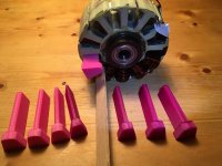
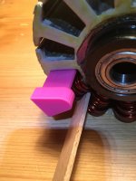
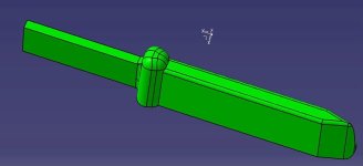
Wedges helped in the winding and geometry is quite good though they will be even better with a slight angle to become thinner on the tip, handles and longer length. I'll update them for tomorrow.

5 down!
image.jpeg
image.jpeg

I must check for shorts tomorrow as i am tough on the wire when shaping it.
 
Project is looking good. Like the wedges. Nice job on those also.
 
Great work from wheazel.
Those wedges are solid, not hollow? Could you possible file down the tip to make it taper to the end to fit your needs better? Guessing a little material off will go along way and not reduce the structure of the wedges too much.
 
Last coil will likely be the toughest and most of the turns will have to be formed without use of wedges or pliers so lots of poking and nudging :D

The carbon prop i ordered on ebay for the thin work never showed up and it will be too late now to order a new one. It'll work anyway!
 
I have started to get twitching/cutoffs on my bike with the other revolt motor. It seems to be current related since it is under load / higher throttle

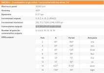
I suspect hall interference or hall errors causing bad signals so i started to assemble the RMC22 rotary commutation encoder for a trial. If it works out then i'll post a guide how to use it.

Winding is paused a while until i have a functioning bike again.
 
Sensor didn't work.. I have asked renishaw if the rmc22 encoder signals will substitute hall sensor signals straight off just to be sure, but I probably broke or shorted one of the connections since the soldering was so difficult. Impossible to tell now as i filled the sensor with silicone rubber :roll:

EDIT: Sheet says commutation signals are "+/-24mA output drive". Does that mean signal goes from +5V to -5V? I guess the controller expects 0V / +5V ?

rmc22 encoder.JPG
View attachment Data-sheet-RMC22-magnetic-encoder (5).pdf
I guess someone with a little more skills in electronics would know.. :?:
I have seen this encoder discussed before here at ES but with no additional data as it was not easy to purchase it then.
 
I received reply from Renishaw:
"The output from RMC22 are digital signals with voltage swing from GND to Vdd."
the encoder should work as a straight replacement for hall sensors. I must have gotten some of the wires damaged in the connections.. I have ordered a new encoder and precrimped leads to avoid any soldering of these tiny crimp contacts.
 
larsb said:
I received reply from Renishaw:
"The output from RMC22 are digital signals with voltage swing from GND to Vdd."
the encoder should work as a straight replacement for hall sensors. I must have gotten some of the wires damaged in the connections.. I have ordered a new encoder and precrimped leads to avoid any soldering of these tiny crimp contacts.

Good investigation work, and good luck with the new sensor.
Do you have any picture of your bike with the motor that is acting up?
 
How much labor do you estimate this will be in total for the rewind? Not counting building tools, and waiting for replacement sensors, mail, etc..

Eagerly awaiting news about the potential of this motor properly built!

Thanks for the effort. It should be educational for many.
 
I guess effective time for me will be something like this:

Disassemble 1
Strip old wire 1
Stator prep 3
Winding 12x1.5
Halls 2
Phase leads connection and coil joining, connectors 4
Assemble 1

Total 30hrs

That seems like a lot but i am a slow builder normally and also first time winder.

If you thought "heck, this guy can't even solder a cable" then here's a size reference for the encoder cables. Thats 20 of them in the bag. 8)
 
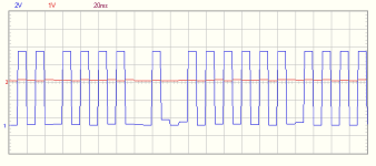
I have decided to try a sensor mount outside the motor since hall signals are distorted, that's a reason for the stalling i get when riding:
Image1.png

I've read several times that the revolt motors are hard to drive.. if signals look like this, no wonder it's hard!

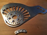
The new motor mount got a slot for the sensor so i can fine-tune the position. It turned out half-ok even though my cutting tool in the mill was really dull. The small piece is the slider for the hall sensors that will be fitted towards the motor.
image.jpeg
 
Set-up? What do you mean?

I ride it 50km total each day to/from work. It's a commuter, so even though the motor does not go well it sort of works. It's quite annoying having to baby the throttle all the time and still get stalling in every acceleration and uphill.

I REALLY hope the wind turns out OK. Otherwise i think i'll have to buy another motor - or stop the ebiking. This is taking too much energy. I'd love to work with a quality motor instead of this piece of sh*t.
 
Back
Top