• Hello ES! We could use some help to get us past the finish line on building the new knowledgebase for the forum.
    Can you donate? Please see our fundraising page. Thank you!

Mini Hiryuu v2 - 1.5kw lightest.bike drive on cheap hardtail

Finally, it's not scorching hot in the morning anymore. So we ride again!

The outlier pendulum pedals are cool because they allow me to reduce seat height about 7mm. But the problem with that is that i get less crank forwardness, and this is a big problem for my size 10 feet.
Going from a rear 1.95" to a 1.5" doesn't fully fix this new problem but it is tolerable over the short 2 mile course i pedaled on.

20250825_104412.jpg

The last cog on this cassette is so tall that i can climb a really steep road on human power. I love this 9 speed wide range setup.

Over a short ride, my legs seem to tolerate the pedals being wider, but let's see how it goes over the long run.
Interestingly, despite the giant hole in the cranks, it doesn't feel strange on the foot.

I think i could go back to a more comfortable 1.95" rear if i added 20mm of fork. Sounds like that will be the next upgrade.
 
Hey, i got a VESC and cycle analyst v2 standalone on this thing.. no throttle icon to be seen.

Are you using 2 degree taper cranks and BB? If so PM me your address and I'll send you a 120mm Chromoly bb.

Hm, they just look like normal square taper cranks here.

For this 120mm chromoly bb, does it have long cups?

Here is what the 123mm BB looks like in the box:

1709671745960-png.348556
 
Sorry not to get back to you sooner! All the "Euro" cups (English) I have are short, made of 7075-T6 with outboard bearings... About the all time worst BB cup for the job! The bearings are killer though.

My BB setup is VERY OLD BMX style (that's because my company was a very old BMX company). I uses 5/8" diameter spindles made from thick wall 4130 tubing or Ti64 bar, turned and milled in-house, then centerless ground and the steel ones get black oxided.

I made them in these lengths"
  • 100mm
  • 105mm
  • 110mm
  • 115mm
  • 120mm
  • 124mm
  • 127mm
  • 130mm
  • 133mm
I then provided a bunch of thick Delrin spacers (1.5mm) and thin alum. spacers (.5mm), and one lock ring. Though I tried to convince everybody that the best way to set up the BB was to use the spacers on the right to set the perfect chainline THEN on the left side to "load the spindle until you think that your tightened left crank arm is just snug enough against the spacers but no side to side slop. it might mean taking off the left crank arm a few times, but once your get it ... You are GOLDEN!

So if you want to try some of the short cups, I'll send you a BB with whatever chrmo spindle you want.

Hey another thing, have you ever thought about getting a higher rise stem then clamping your handle onto it with the upper cross bar? that way you can mount your phone, light, bell at the regular stem/ handlebar mounting location and the "stuff" would be tight and protected.

Anyway just a thought.
 
Thanks for the offer, but, i don't think they'll work, they have to be very long to clear the thick plates well.


Hey another thing, have you ever thought about getting a higher rise stem then clamping your handle onto it with the upper cross bar? that way you can mount your phone, light, bell at the regular stem/ handlebar mounting location and the "stuff" would be tight and protected.

Anyway just a thought.

I'm sorry, i can't visualize that. Got a pic?

I've considered mounting the screens and phone on the lower bar of the bmx handlebars for their protection; for now i want the best view of them i can get while i'm still tuning things :)
 
Sorry about the crappy picture. Basically, the tight crankarms "sandwich" the spacers (thick: black Delrin & thin: aluminum) & whatever else you care to add outside of the bearing cups. VERY versatile, especially with all the different lengths of spindles. The picture shows both a Chromo & Ti spindle.

20250830_134340.jpg
 
Hmm, these are interesting, but i have a big pile of bottom brackets from my decades of experimentation already 😅
Much too shallow of cups to help in this case. They're cool, though.
 
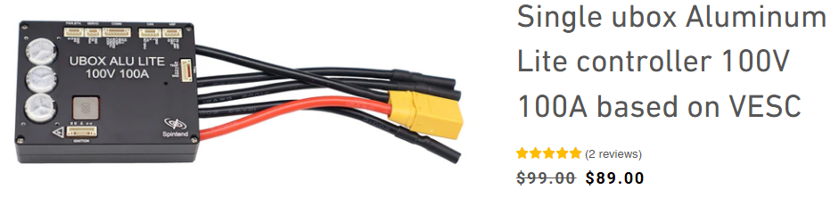
Hey Neptronix, I've been looking at VESC. Looks like you used this board, is that correct? Kind of looks like you can go without this board if the VESC can receive brake and throttle input like this...


single_ubox_100v_for_diy_escooter_application1_41405c77-8676-449c-8b32-97b8e164915c.jpg


Just curious why the ADC board would be used when you can connect right to the VESC. I do see the note about the 10k resistor, maybe that, alone, is reason enough. Or maybe you have a totally different board strapped to the VESC.
 
Yeah, i bought the ewheel adapter because i wanted a brainless plug and play experience. I haven't fully utilized it though ( it would be nice to use the 3 speed switch function )

In hindsight, maybe i should order a 10k resistor. Did you find any instructions on what wire to put it on?
 
In hindsight, maybe i should order a 10k resistor. Did you find any instructions on what wire to put it on?
No. Only from the above diagram. Looks like the resistor goes between the ADC2 and 3.3v. I think this is for high level brake. They seem to be 3 wire sensors. I know low level brake is just a NO switch at the lever and is 2 wire.

I do like that board though. There are many inputs and you can even have turn signals. This seems really great for 4 wheel builds, like a go kart.
 
Yeah. i couldn't find sufficient details. Not exactly knowing what i need to do isn't confidence inspiring. i can't find any 3.3v throttles that fit a bike handlebar either.
 
Ahh, ok. That looks like another good reason to use that ADC board. I see it has 5v on the brake and throttle. Did you connect your throttle and brake to that board?
 
i can't find any 3.3v throttles that fit a bike handlebar either.
Any potentiometer throttle is an any-voltage throttle. ;)


If a hall throttle uses a hall capable of operating down to 3.3v, it could be used.

Or if you wanted the experimental experience, and have the time to waste, you can change out the sensor of one that requires higher voltage for one that doesnt'. There are a number of 3.3v-capable ones around, so as long as they operate off the same magnetic / gauss range to work with the same magnets already in the throttle to give the correct voltage range. (that requires knowing which sensor is in the throttle and finding it's data sheet to compare it's response to the 3.3v versions you'd be considering).
 
Last edited:
Yeah, i bought the ewheel adapter because i wanted a brainless plug and play experience. I haven't fully utilized it though ( it would be nice to use the 3 speed switch function )

In hindsight, maybe i should order a 10k resistor. Did you find any instructions on what wire to put it on?
It says in the image to put it between ADC2 (brake input signal wire) and 3.3v. This implies that like almost all ebike controllers, it acts as a pullup resistor, so that a simple switch can be used to ground the brake line for on/off brake control (instead of using the analog braking capability for full variable regen).
 
Ahh, ok. That looks like another good reason to use that ADC board. I see it has 5v on the brake and throttle. Did you connect your throttle and brake to that board?

Yes, that's the idea.

It says in the image to put it between ADC2 (brake input signal wire) and 3.3v. This implies that like almost all ebike controllers, it acts as a pullup resistor, so that a simple switch can be used to ground the brake line for on/off brake control (instead of using the analog braking capability for full variable regen).

It's quite confusing as to why i'd do this. here's a visualization of how i'd add this resistor:
2025-09-14 05_45_36-Window.gif

The wiring makes sense to me because the phaserunner is wired similarly.

The modification does not. It seems like this may permanently engage the ebrake switch.

I also don't understand why we are taking the 3.3v line and reducing it's voltage. We have a throttle that expects 5v, but we're giving it 3.3v minus some volts. why?

The more i search google on this, the more confused i get. For example:
ADC Throttle Voltage Issue | VESC Project

You should connect the throttle to3.3V. The pin on the STM processor is not 5V tolerant! Then you calibrate the throttle, so that full voltage is 100% and minimum voltage is 0%.

This makes sense. I'm assuming that in this case, we are taking a 5v throttle and connecting it to the 3.3v line and adjusting the throttle curves/start/stop to compensate.

There should be a 10K resistor in between ADC1 and GND, close to the port of the VESC controller. If the cable gets damaged, the resistor will pul the signal low ( 0% input).

This makes it sound like an added safety feature and not a way to make a 5v throttle work at 3.3v

What i do know:
If you connect 5v to the throttle or brake line, you're going to blow the microcontroller.

The spintend ewheel adapter scales up and down the voltage for you, go ahead and plug the 5v thing into it, no problem.
 
It's quite confusing as to why i'd do this.
The only reason I know of is if you are not using variable regen, and just want an on/off brake, and the AD2 line is used for the brake input, and you are using a simple switch for the brake input.

Because the AD2 line is analog input, it does not (cannot) have an internal controller pullup like a typical on/off braking type controller would already have, so you have to add one. Without a pullup, there is no signal for the controller to detect. With a pullup, the controller will see +V all the time on the input except when braking, when it will see 0V, so now it has a signal to work with.

If you are using an analog input for braking, like a second throttle, or an analog-output brake lever such as those Grin sells, or something like I use (a regular brake lever pulling the cable of a cable-operated throttle), then no pullup is needed or wanted.

here's a visualization of how i'd add this resistor:
View attachment 377379

The wiring makes sense to me because the phaserunner is wired similarly.

The modification does not. It seems like this may permanently engage the ebrake switch.
If the ebrake is not programmable in level, so that it can only respond to a full +V as "on", then yes, it would. In that case the fix is simple--wire the 10k resistor from ADC2 to ground, and the brake switch from ADC2 to 3.3v.

If it is programmable then set it for 0V = on, and full +V as off, and wire it as diagrammed.


I also don't understand why we are taking the 3.3v line and reducing it's voltage. We have a throttle that expects 5v, but we're giving it 3.3v minus some volts. why?
Because the VESC is a 3.3v device, then you put a 5v signal from a 5v throttle into it you will damage it. (you already know this, as stated further down ;) ).

The mod with the resistor is on the AD2 line, for braking. The throttle input, AD1, doesn't get a mod (not that I can see anywhere in the diagram, at least). It's wired just like it shows--3.3v to supply the throttle (instead of 5v), ground for ground, and it take the throttle input signal as-is on it's signal input, AD1. Most of the analog (linear, or ratiometric) hall sensors I've dealt with split the +V supply for the center (off) point and it just goes up and down from there, so there is no need to modify the signal for the lower input voltage or the lower voltage range capability of the VESC inputs.

The only thing required (as you already noted) is like any other controller wiht programmable throttle voltage range / throttle response, and that's to tell (calibrate) the controlller to the actual available range of throttle output. (you do this for the Phaserunner as well, or the Cycle Analyst)


This makes it sound like an added safety feature and not a way to make a 5v throttle work at 3.3v
EDIT: Just to be very specific in case any readers haven't realized this: The 10k from AD1 to ground is a separate thing from the 10k from AD2 to 3.3v.

The 10K from AD1 to to ground *is* a safety feature, to prevent the "broken ground causes WOT runaway" issue. It is something that could (should) be built into all controllers, but isn't part of any of them that I'm aware of. :(


FWIW (pedanticness for future readers, just in case): there isn't any way to make a 5v throttle, that actually requires 5v, to work on 3.3v. You can supply it with 5v, and then downconvert / scale the output (opamp is the easy way) to 0-3.3v range, but that doesn't actually make it work on 3.3v...just makes it compatible with it. That's what that adapter board does.


Hopefully I'm not missing something in the diagram or the desired functionality; if not then the above should be correct.
 
Last edited:
i can't find any 3.3v throttles that fit a bike handlebar either.
Yeah, they aren't a thing. You do one of three four things:

1) Wire it to 3.3V+ line for positive (every hall throttle I've used has been fine with this.)
2) Wire up a voltage divider to scale the 5v down to 3.3v range
3) Use the adapter thing (which is, basically, #2, but already done for you)
4) Screw it and feed the VESC the returning 4.2v on the ADC1 -- some controllers will fry at this, but quite a few are built to actually handle this. The controller will not see the voltage above 3.3v (so you lose a lot of throttle range), but it doesn't fry the board either.

I've done every one of these methods.
 
Last edited:
Hey man, thanks a lot for your experience.

Does a mechanical on-off switch work on the brake line without any modification?
Would you advise doing the 10k resistor trick also?
 
Does a mechanical on-off switch work on the brake line without any modification?
Would you advise doing the 10k resistor trick also?

I've use plenty of "2 wire, red plug" run-of-the-mill brakes on ADC2, yes. (My personal favorite, which the CA also does, is that ADC2 going active switches the ADC1 into proportional regen mode; but there are plenty of other ADC modes as well, constant brake force, etc.)

As for the 10k part:


Their diagram is basically yours! ;)
 
Ooooooh, this page looks recent, and VESC forums weren't helpful, that's why i'm in the dark about this.
Thanks so much for this link. I'm going to pass this on.
 
Hey man, thanks a lot for your experience.

Does a mechanical on-off switch work on the brake line without any modification?
Would you advise doing the 10k resistor trick also?
If you use a switch instead of an analog voltage source for braking control, you *must* add the pullup (or pulldown) resistor, for the reasons previously noted.

Whether you use pullup or down and whether you wire the switch from signal to ground or +V depends on how you setup the braking input to react (to a low or a high), assuming it's capable of being user-set.

If the system is a DD hubmotor, the braking would be better as variable regen controlled from a variable input as previously described. I personally find it less instinctive and difficult to remember in critical situations if using the actual throttle as the braking control. My brain and muscles expect the go-thingy to go and the stop-thingy to stop, and if the go thingy also stops sometimes but only if I do certain things that's too many things to deal with during emergency or other critical no-think-brain-disconnected-happens-too-fast-to-do-anything-but-react situations. ;)


If the system is a middrive or other non-electric-braking-capable system then the only thing you're using the braking control for is to shutdown the motor, so a switch works fine. You'd probably disable regen (if possible) as it wouldn't do anything functional.
 
From the linked VESC page itself:

How to connect a 'button' device to ADC pin to implement a brake?​

Unfortunately, VESC only accepts the ADC signal to make braking. But the common e-bikes are using a switching handle to give the brake signal to controller.


So we have to simulate a ADC signal to VESC, according to the handle-switch state. The limitation of this solution is that we can only simulate two fixed voltage states: high and low.


Wiring:​

We need an extra 10K ohm resistor.
simulate%20ADC2%20brake%20for%20brake%20handle.png

On two pins of the switch, one connect to GND, one connect to ADC2 pin of the Comm port. THEN, on the two pins of the 10K ohm resistor, one connect to the ADC2 pin of the Comm port, one connect to the 3.3V(or VCC/VDD) pin of the Comm port.
Config in VESC tool: choose 'Current No Reverse Brake ADC2' control type, or other type with 'ADC2' in its name.
And don't forget to invert the ADC2 input.
invert the ADC2 input


Back
Top