T.J.L. said:
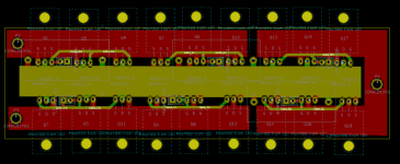
I created a quick layout in KiCAD. It's made with TO-220 footprints since I did not have a suitable TO-247 footprint and it does not contain all the resistors, capacitors etc. Actually the FET legs might also be wrong order but it really does not matter now. What do you think about this kind of layout? The power buses run in the middle with phase A FETs above them, phase B FETs below the buses and phase C FETs on the right. The phase wires could be soldered on the front layer zones above the FETs. The three large caps are placed right next to (partly on top of) the power buses.
View attachment 1
This kind on layout would allow for the fully laminated power bus, however the phase currents travel a bit longer route on the pcb. Especially when I would build this with five FETs in parallel instead of three like in this example. This would be quite a different approach to the
one proposed by Lebowski. What are your opinions?
What about your next fully laminated layout zombiess? Mind sharing it so we can all give it some thought?
You have the understanding of a laminated bus, that's a rule and a very big one. This is a very difficult game to play without knowing the rules and scouring the internet will only provide bits and pieces with large chunks missing. This site has more info than any other location I've seen, but it's very hard to find all the good stuff since without having a feel for the rules it's hard to discern good info from bad

A classic chicken/egg scenario. My build threads and Arlo1's build thread has good info, I'd stick to HighHopes comments for the most part.
I've been compiling notes (well over hundreds of pages to sort through) from discussions I've had with the knowledgeable designers on this site. The largest contributor being HighHopes who has been doing this for > 10yrs in an industry that has VERY high specs to meet. I'm also adding my own notes as my understanding grows, I'm passionate about this field and have started digging into the details. It sounds like you have a strong interest as well based on your questions.
My first build took me an entire year of him tutoring me several times per week and I didn't start off as the most patient but quickly changed my tune once I saw how valuable it was. I'm trying to pay it forward myself now and feel pretty confident about the basics. It works quite well. My 2nd build (this thread) is a vast improvement and my upcoming 3rd/4th builds will be yet another leap.
The new bus bar layout will feature water jet cut copper 1/8" thick, 0.75"-1.00" wide DC bus bars separated by kapton tape. Only a small fraction of the bus will not be laminated. They will be placed on the same side of the PCB allowing phase out bus bars on the other side to resist PCB warping and facilitate high current output. I'm sorry I don't have a diagram yet as I'm no 3D modeler.
Since you asked for a critique on your layout, here it goes.
You are at the same design issue I was in about 1yr ago, parallel devices really limit layout choices. It took me a long time and many iterations to come up with what you see in this thread and it's only been in the last 4 months that I figured out how to improve on it and meet the fully laminated layout design rule. For low power <1kW to probably 5kW you can get away with bad rules. Heck I've done short bursts of 25kW @125V on a Xie Chang 36 MOSFET controller which has an atrocious layout and the worst gate driver performance I've seen (now that I understand what I'm looking at), but I wanted something better.
Your DC bus layout will work fine, I did the same style on my first controller, one on top of the PCB, one on the bottom. The issue is the phase output and the gate trace routing. Each gate trace needs to be over it's respective ground reference to prevent the stray inductance in the gate traces from picking up the EMF and converting it to voltage. That voltage can then raise to the gate threshold causing an adjacent non active bank to turn on causing a shoot through event. The gate driver design / layout is critical to the success of any controller. Your gate traces violate the rule of never routing them into the power pass section. The power pass is your DC Link and phase output (all the power passes through these areas). It looks like you planned to use twisted pair to connect to the gate traces, that's allowable since the gate signal has it's respective ground reference.
I see what looks like some large caps, I'm guessing they are DC Link? What about the snubber caps? It might be better to place DC link caps right at the entry of the battery pack feeds. I'm not sure and I think I remember HH and myself discussing this and we ended up undecided on if it was OK, but he has never done it before. He has also had limited experience with paralleling which has lead to some interesting discussions on some findings I've made and he added additional info I didn't know that was happening (all positive effects). IMO it's OK to distribute down the bus, I know it works as Sevcon does it with lots of little electrolytic caps and no DC link caps (not a fan of this), but it's certainly functional and appears to work (works = functional + reliable). One issue that could happen with running them down the bus is any stray inductance could setup ringing between the caps on the bus. I personally have not seen this during testing, but my designs are fairly low inductance. I'd suggest copying my layout as it allows for low profile and a large heat spreader or heat sink to be utilized and I spent a lot of time figuring out what looks like an obvious layout (rules and details). I'm very fond of mounting the MOSFETs flat. It is important to keep all parallel MOSFETs on the same thermal mass. Looks like you'll be mounting them all on the same sink which is good.
You also might want to tie your gate pin to your source pin with a resistor if you haven't done so already. Somewhere around 4.75k is usually good. The reason to do this is to control the state of the gate during power up/power loss. HH gave me the math to prove this, but I think it or myself has an error. The goal is to make sure you can control / know what state your gate is in at all times aka what happens if your gate driver loses power while running, will something pop?
Symmetry is also important, keep that in mind when designing. Everything about power electronics is detail oriented, so many rules. HighHopes an myself have plans to write a how to, but we both need some more free time as it's not going to be a short story. I'm already collecting information by keeping good notes and snagging the math from white papers, thesis papers, app notes, etc to justify design choices.


