The New Cadence Sensor Code
As many of you know I have been trying to figure out how to best increase the feeling and response of the entire system. The cadence sensor is one small part of the development but is very important part nonetheless. Especially at startups, when shifting gears and also when you stop pedaling and the motor is supposed to disengage. The time delay in the latter situation is often called the power-off-lag. In short, a good cadence sensor implementation provides a safe and responsive system.
Startups: We need to confirm that the user is rotating the pedals to enable assistance. So we do this by increasing the minimum cadence measured by the system and thus get a more responsive startup. But in doing so we also introduce a time delay as the system needs to wait for the transitions. We partly solve this by optimizing the code overall. But, in some situations, there might still be a considerable delay between the moment the user stops pedaling to the moment the motor stops giving assistance. This is the power-off-lag.
Power-off lag: To solve the power-off-lag we change the resolution and therefore the response time depending on wheel speed. No point in measuring down to 5 RPM and waiting for transitions when going fast. For instance, if we are going at a speed of 20 kph, or almost 13 mph, with a gear ratio of 52 to 11 teeth, the crank cadence is around 30 RPM.
So now, the resolution will automatically adjust appropriately and we get a much faster response.
What more can we do?
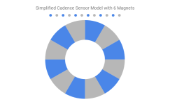
This is a very, very, simplified model of a cadence sensor disc with 6 magnets and the transition states for a complete revolution. Note that the TSDZ2 has 20 magnets in its cadence sensor disc but we are keeping it simple with only 6 magnets:

The blue fields represent the magnetic fields strong enough to measure as HIGH in the system. The grey fields represent the opposite and is measured LOW in the system. There is a magnet in the center of all the blue fields.
Usually, when calculating the rotational speed of the crank you measure the time between two transitions and take in to account the number of transitions there are in the cadence sensor disc. The transitions that are measured are often of the same kind. One example of transitions of the same kind is when the cadence sensor pin state is going from LOW to HIGH. In our example this means we only count the transitions that go from GREY to BLUE. We discard the transitions that go from BLUE to GREY.
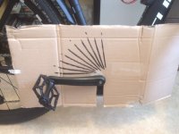
I was curious of using all the transitions but knew that if the spacing between the different transitions was not the same it could be problematic. So I tested for every transition and got this, which I also posted previously in the thread:

It looked like we had a nice distribution of transitions and it seemed the spacing was the same between all transitions. So this made me very happy as we could just make one very small change and immediately half the response time. But this was not the case.
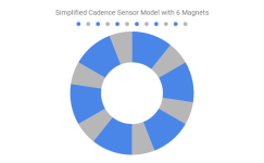
Following is an exaggerated version of the reality where I want to make it very clear what problem we must solve. Firstly, here we have strong magnets in the cadence sensor disc. So the spacing between LOW to HIGH -> HIGH to LOW is longer than the spacing between the HIGH to LOW -> LOW to HIGH.

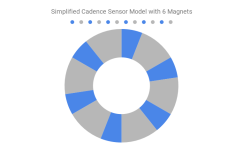
Secondly, here we have weak magnets in the cadence sensor disc. So the spacing between the LOW to HIGH -> HIGH to LOW is shorter than the spacing between HIGH to LOW -> LOW to HIGH.

So let us call this discrepancy a difference in magnet pulse width. Sadly, this value is different for every cadence sensor. Meaning calibration is needed for every user that wants to have the more responsive cadence sensor. I had the opportunity to test on two different TSDZ2 units, one very old and one completely new. One unit got 67 % HIGH and 43 % LOW and the other 40 % HIGH and 60 % LOW.
With clever code we can make this all work very nicely and have the equivalent of 40 magnets. Making the cadence sensor react faster, with less rotation to engagement and make the overall system more responsive.
What I wish to do today is an automatic calibration process. The user will be able to choose between the standard or extra cadence sensor mode. If the user chooses the extra cadence sensor mode a small calibration process is needed but the TSDZ2 will manage everything. The user only needs to hold one button and it is all configured automatically.
So if no one minds I will try to add this automatic calibration process and save a lot of time writing a tutorial with tips and tricks. As it will all be done automatically. So in the long term this will probably be more time efficient and will result in an even better experience for users.
Another reason this is especially important to do is that it can greatly help users that use the coaster brake version. Where it is very important with a fast response. So I hope everyone understands why I want to implement the automatic calibration process instead of the manual calibration. Do note that I will continue to work several hours per day with the development until the beta is out!
As many of you know I have been trying to figure out how to best increase the feeling and response of the entire system. The cadence sensor is one small part of the development but is very important part nonetheless. Especially at startups, when shifting gears and also when you stop pedaling and the motor is supposed to disengage. The time delay in the latter situation is often called the power-off-lag. In short, a good cadence sensor implementation provides a safe and responsive system.
Startups: We need to confirm that the user is rotating the pedals to enable assistance. So we do this by increasing the minimum cadence measured by the system and thus get a more responsive startup. But in doing so we also introduce a time delay as the system needs to wait for the transitions. We partly solve this by optimizing the code overall. But, in some situations, there might still be a considerable delay between the moment the user stops pedaling to the moment the motor stops giving assistance. This is the power-off-lag.
Power-off lag: To solve the power-off-lag we change the resolution and therefore the response time depending on wheel speed. No point in measuring down to 5 RPM and waiting for transitions when going fast. For instance, if we are going at a speed of 20 kph, or almost 13 mph, with a gear ratio of 52 to 11 teeth, the crank cadence is around 30 RPM.
So now, the resolution will automatically adjust appropriately and we get a much faster response.
What more can we do?
This is a very, very, simplified model of a cadence sensor disc with 6 magnets and the transition states for a complete revolution. Note that the TSDZ2 has 20 magnets in its cadence sensor disc but we are keeping it simple with only 6 magnets:

The blue fields represent the magnetic fields strong enough to measure as HIGH in the system. The grey fields represent the opposite and is measured LOW in the system. There is a magnet in the center of all the blue fields.
Usually, when calculating the rotational speed of the crank you measure the time between two transitions and take in to account the number of transitions there are in the cadence sensor disc. The transitions that are measured are often of the same kind. One example of transitions of the same kind is when the cadence sensor pin state is going from LOW to HIGH. In our example this means we only count the transitions that go from GREY to BLUE. We discard the transitions that go from BLUE to GREY.
I was curious of using all the transitions but knew that if the spacing between the different transitions was not the same it could be problematic. So I tested for every transition and got this, which I also posted previously in the thread:

It looked like we had a nice distribution of transitions and it seemed the spacing was the same between all transitions. So this made me very happy as we could just make one very small change and immediately half the response time. But this was not the case.
Following is an exaggerated version of the reality where I want to make it very clear what problem we must solve. Firstly, here we have strong magnets in the cadence sensor disc. So the spacing between LOW to HIGH -> HIGH to LOW is longer than the spacing between the HIGH to LOW -> LOW to HIGH.

Secondly, here we have weak magnets in the cadence sensor disc. So the spacing between the LOW to HIGH -> HIGH to LOW is shorter than the spacing between HIGH to LOW -> LOW to HIGH.

So let us call this discrepancy a difference in magnet pulse width. Sadly, this value is different for every cadence sensor. Meaning calibration is needed for every user that wants to have the more responsive cadence sensor. I had the opportunity to test on two different TSDZ2 units, one very old and one completely new. One unit got 67 % HIGH and 43 % LOW and the other 40 % HIGH and 60 % LOW.
With clever code we can make this all work very nicely and have the equivalent of 40 magnets. Making the cadence sensor react faster, with less rotation to engagement and make the overall system more responsive.
What I wish to do today is an automatic calibration process. The user will be able to choose between the standard or extra cadence sensor mode. If the user chooses the extra cadence sensor mode a small calibration process is needed but the TSDZ2 will manage everything. The user only needs to hold one button and it is all configured automatically.
So if no one minds I will try to add this automatic calibration process and save a lot of time writing a tutorial with tips and tricks. As it will all be done automatically. So in the long term this will probably be more time efficient and will result in an even better experience for users.
Another reason this is especially important to do is that it can greatly help users that use the coaster brake version. Where it is very important with a fast response. So I hope everyone understands why I want to implement the automatic calibration process instead of the manual calibration. Do note that I will continue to work several hours per day with the development until the beta is out!

