• Hello ES! We could use some help to get us past the finish line on building the new knowledgebase for the forum.
    Can you donate? Please see our fundraising page. Thank you!

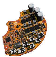
VESC based INNOTRACE M620 Simple motor controller

I'd be interested in buying 1-2 controller(s) if someone orders 5 of them assembled from JLCPCB and wants to get rid of them extra ones. Preferrably as flashed :). Located in Finland so it'd probably have to be EU-based.

That someone might be mine later on, but gauging interest!
 
So.. that's it? No bugs/problems? Nothing to improve in the first iteration? 😷🥸
No, it works just fine. I will fix some notes and typos in the KiCAD schematic, add a firmware file with lowered absolute maximum current value (the suggested firmware file absolute maximum current is probably too high for the specified MOSFETs), update the Readme.txt file information and add some extra CAD models for convenience. But the fabrication files are the same with no any updates.
 
Last edited:
What am I gonna do with all those controllers?

1785965120195.png
Don't you want to sell the controllers, you've received already first, before someone has to order the next 5 pieces and then has four, that he doesn't need also?
5 is the minimum order quantity at JLC PCB....

And you have to remember that you need a STLink to flash the firmware the first time. After that, you can use the VESC tool and flash by UART or CAN. Or am I wrong?
 
Last edited:
You can order only 2 assembled, that's the minimum quantity. (Plus you'd get 3 bare PCBs). But it is more viable to purchase 5 assembled, and then re-sell. I'm sure there'd be interested people here!
 
Don't you want to sell the controllers, you've received already first, before someone has to order the next 5 pieces and then has four, that he doesn't need also?
5 is the minimum order quantity at JLC PCB....
Yeah, I was thinking about it. But at least for the first unit we need to find a reputable and active long member from this forum from the US familiar with VESC firmware who will dig into it to investigate that loose drivetrain impact wrench effect on throttle from stand still and modify the VESC firmware to get rid of it. Of cause that person needs to have that motor and ideally be capable to build a battery can feed that controller with hight voltage and hight current.
 
why would you need to do that if you're just doing a "group buy" basically? and not becoming an official re-seller of anything xd
 
to investigate that loose drivetrain impact wrench effect on throttle from stand still
I wondered, that you are using sensorless start in your video, where the encoder is not in place. Sensorless start under load is a difficult. Have you tried sensored start then switch to sensorless?
Adding a function, that preloads the chain with low current before forcing the current that is demanded by the throttle position, should be quite easy...
 
Last edited:
And you have to remember that you need a STLink to flash the firmware the first time. After that, you can use the VESC tool and flash by UART or CAN. Or am I wrong?
The fist time you flash the controller with St Link V2. After this you can flash firmware files using VESC Tool. To connect VESC Tool to the controller you can use a Bluetooth dongle (like I did), or you can use a VESC Express CANable dongle (with WiFi, USB or Bluetooth), or you can use USB a cable.
 
I wondered, that you are using sensorless start in your video, where the encoder is not in place. Sensorless start under load is a difficult. Have you tried sensored start then switch to sensorless?
Adding a function, that preloads the chain with low current before forcing the power that is demanded by the throttle, should be quite easy...
On the video I set it to sensorless mode just for test and demonstration. But in the motor it is set to encoder mode and it is set to encoder mode by default in the firmware.

The encoder works, and it works great and 100% reliable even under load from stand still. The "impact wrench" effect starts only if there is some slack in the drivetrain so the motor starts rotating with no resistance and then suddenly hits the wall, and that wall not only stops it but also bounces back due to the high gear ratio and chain swing.

Also this effect appears only in current control mode and it works fine in duty control mode. Unfortunately the torque sensor does not work in duty control mode. Maybe this is the key to solving it, maybe the firmware can be modified the way it works like combination of those two modes. For instance the torque sensor works in current control mode (since it works OK) and the throttle works in duty cycle control mode.
 
For example I myself am going to build a throttle-only at 20S, so the torque sensor not working (in duty control mode) is a non-issue for me.
Also save some money because my current motor is UART and I don't have to buy the relatively expensive CAN torque sensor.

The motor will run fine without a torque sensor attached, right?

Are there any other "behavioral" differences when running throttle-only, when comparing current control and duty control mode?
 
why would you need to do that if you're just doing a "group buy" basically? and not becoming an official re-seller of anything xd
Because of we still got work to do. The first controllers need to go to someone who can help the community.
 
Because of we still got work to do. The first controllers need to go to someone who can help the community.
So you're saying if I order 5 I would need to pick and choose who to sell to? =D I mean you're free to do that with the 5 you have, and seeing as you're US-based it would be a no-go for us in EU anyway.

I am interested if someone in the EU is going to order 5 and sell their extras :).
 
For example I myself am going to build a throttle-only at 20S, so the torque sensor not working (in duty control mode) is a non-issue for me.
Also save some money because my current motor is UART and I don't have to buy the relatively expensive CAN torque sensor.

The motor will run fine without a torque sensor attached, right?

Are there any other "behavioral" differences when running throttle-only, when comparing current control and duty control mode?
Yes, it should work with throttle only too.
 
So you're saying if I order 5 I would need to pick and choose who to sell to? =D I mean you're free to do that with the 5 you have, and seeing as you're US-based it would be a no-go for us in EU anyway.

I am interested if someone in the EU is going to order 5 and sell their extras :).
I was talking about only the 4 extra units I have. I can not tell you what to do with your controllers. But if there is a reputable long member on the forum familiar with VESC who would like to have it and figure out the VESC firmware we might prioritize that person for sure.
 
Last edited:
not only stops it but also bounces back due to the high gear ratio and chain swing.
This is an oszillation of the motor current PI control, we have that issue with the EBiCS firmware on the original Bafang hardware also, if you demand too much current from standstill.
Tuning the PI parameters could help, but the save way will be to preload the chain with low current first, so this bouncing can't happen.
Bosch calls this feature the Drivetrain Tensioner (part of the Performance Upgrade 2.0 / smart system updates). It uses software control to pre-load or engage the freewheel and eliminate chain slack the moment you stop pedaling backwards or lose chain tension, giving you instant power delivery and stopping the loud "clunk" sound.
In duty cycle mode, there is no PI current control, so the bouncing can't happen. But you have no control on the torque either.
 
Last edited:
Maybe slightly offtopic (since it's not VESC) but I have no problems with "chain slap" in my BBSHD. Running the open source firmware, but without chain pretension. But I have set my current ramp to 5A/s (but it's shunt modded - so 10A/s) and start current 1% (Global max current 25A = shunted 50A) . No idea if it's "duty control" or "current control".

Also my M620 Innotrace friend really liked the throttle and said "wow that's smooth" ;)
 
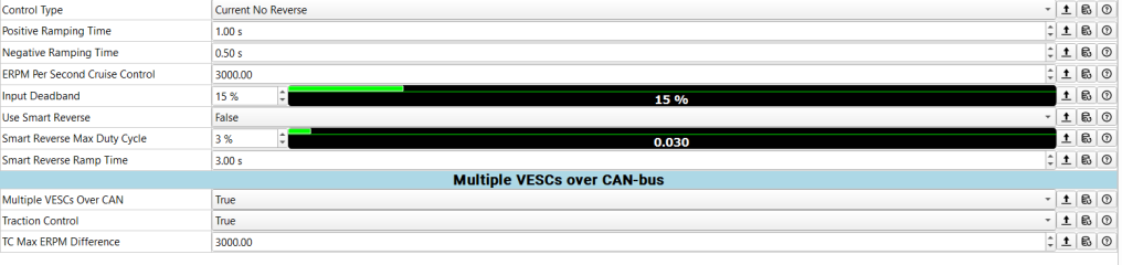
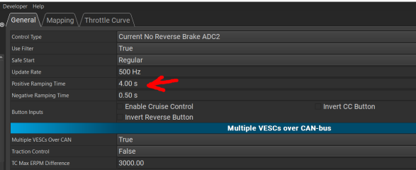
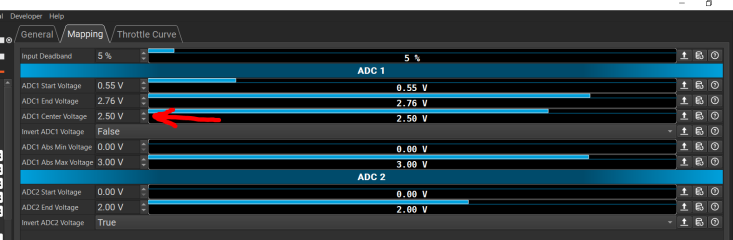
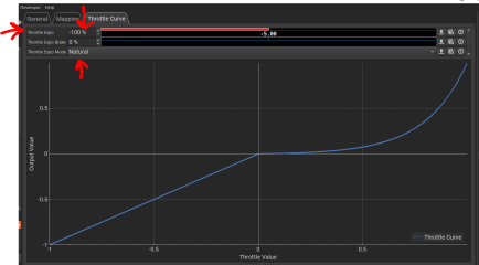
These are the settings I tried and the impact wrench effect still appears. It appears in all support modes except Eco and walk mode.

1786302764398.png

1786302882493.png

1786302940955.png
 
Last edited:
I run some agent farm on the software and reported issue... still waiting for my bike to build but maybe you can find anything helpful here


The full report: Claude Artifact

AI agent farm analysis of the M620 / VESC "impact wrench" throttle issue

I ran a farm of AI agents through the complete M620/VESC setup: configuration files, firmware source, throttle/PAS command paths, current control, duty control, encoder behaviour, current limits and possible mechanical causes.

The agents reviewed the shipped VESC source line-by-line, challenged different root-cause hypotheses and produced a measurement-led RCA plus a proposed test/fix plan.

Short version:

The main hypothesis is that the throttle is not simply applying too much torque.

It is allowing the motor to build too much speed while drivetrain slack is still open.

In current-control mode there is nothing directly bounding motor speed during this unloaded phase. The rotor can therefore accelerate very quickly on only a few amps. When the chain/freehub/gearbox slack closes, that stored kinetic energy suddenly hits the drivetrain.

This also explains why duty mode behaves materially better: VESC clamps the modulation/duty, which effectively limits the voltage available to the motor and therefore bounds the free-spin speed before the drivetrain engages.

The existing 4-second throttle ramp helps, but it only reduces current/impact energy — it still does not create an actual speed ceiling.

Important: this is still a strong mechanism hypothesis, not a proven root cause. We do not yet have a telemetry capture from the affected bike, and the first step is verifying that the configuration archive actually matches what is flashed on the controller.

Other things found during the source/config review:

  • Throttle and PAS are configured very differently: throttle positive ramp is 4.0 s while PAS is only 0.3 s.
  • The throttle ramp is relative, meaning its actual A/s rate changes with assist level.
  • Drive current is +160 A while negative motor current is only −20 A, so rebound-opposing authority may be much smaller than drive authority.
  • Stock VESC already contains two potentially useful low-speed limiting features: foc_start_curr_dec and l_duty_start, but both are effectively disabled in the current configuration.
  • The encoder→observer handoff is not the likely cause because the handoff occurs around 30,000 ERPM, far above this launch event.
  • Throttle mapping itself is already extremely soft: with exp = −5, 10% throttle travel produces only about 0.44% command.
  • Current-loop PI oscillation is still technically open, but there is not enough evidence to justify changing PI gains blindly.
  • Mechanical backlash/freehub/gearbox slack remains an important possible co-factor.

Before changing firmware — proposed config-only experiments

The nice part is that several useful experiments can be done directly in VESC Tool without rebuilding anything.

A. Start Current Decrease — best first test

Enable the stock foc_start_curr_dec feature.

Suggested initial sweep:
Code:
foc_start_curr_dec = 0.10 – 0.25
foc_start_curr_dec_rpm = 2500

For example, 0.10 would allow roughly 10% of the normal current ceiling at zero RPM and progressively restore full current by 2500 ERPM.

If this removes the hammering while hill/loaded starts are still acceptable, it might even be a usable config-only solution.

The downside is reduced standstill torque, and it affects PAS as well.

B. Duty-based current foldback

Test l_duty_start below 1.

This reduces current as duty rises and is therefore the closest stock configuration feature to a speed-sensitive limiter.

Very useful diagnostically, because if this stops the problem while Start Current Decrease does not, it strongly supports the idea that limiting motor speed/voltage is more important than simply limiting initial torque.

It is not recommended as the final shipped setting, because it is global and would also reduce current during normal riding at higher duty.

C. Increase |l_current_min| — only if logs show duty reversal

Current configuration:

Code:
l_current_max = +160 A
l_current_min = -20 A

If the motor is actually reversing duty/current during the rebound, the −20 A limit may restrict electrical damping.

Increasing its magnitude may shorten the ringing, but it cannot prevent the first impact.

This should only be tested after confirming reversal in telemetry, and only inside reduced test-current limits.

D. PAS ramp experiment

PAS currently uses 0.3 s positive ramp versus 4.0 s for throttle.

It is worth trying a slower PAS ramp to understand the interaction, but this is mainly a rideability/tuning experiment and not considered the root fix.

E. Duty mode

Duty control is already the known-good fallback for throttle launches.

It can be a perfectly valid solution for a throttle-focused bike, but it changes torque-sensor/PAS behaviour and therefore is not considered the ideal product solution here.

Recommended firmware direction

If the captures confirm the RCA, the preferred software solution is now:

F4 — current control + throttle-derived duty clamp

The idea is to stay in current-control mode but additionally impose a temporary throttle-derived maximum duty.

That gives us both:

  • normal current/torque control,
  • full standstill torque capability,
  • but also a voltage/speed ceiling similar to the behaviour that makes duty mode work better.

Conceptually:

Code:
max_duty = d_floor + throttle * (l_max_duty - d_floor)

So low throttle corresponds to a low allowed duty/speed, and as the rider requests more power the duty ceiling opens progressively.

This should apply only when throttle is actually the controlling source, not when PAS is supplying the command.

The report proposes implementing this with a dedicated motor-interface duty-clamp setter plus a timeout/failsafe so a stale application command automatically restores normal max duty.

Other firmware ideas

F5 — explicit slack detection / preload

A more advanced option:

Code:
IDLE
↓
PRELOAD
↓
ENGAGED

During PRELOAD the controller would gently take up drivetrain slack, then release full power once engagement is detected from ERPM acceleration/rotation/time.

Potentially the best subjective behaviour, but also more complex because reliable slack detection is the hard part.

F3 — speed-feedback damping

Another investigated idea was subtracting current as motor speed rises:

Code:
iq_out = max(0, iq_cmd - kd * omega)

This can soften gentle launches but the final analysis concludes it has too little authority to be the primary fix at high assist/current levels.

It may still be useful as a LispBM experiment, but it is no longer the recommended architecture.

Two additional firmware clean-ups

S1 — level-independent throttle ramp

Currently the same "4 second" throttle ramp corresponds to very different real A/s depending on assist level.

Example from the current setup:

Code:
Eco:    ~4.4 A/s
Level 9: ~40 A/s

The proposed source change scales ramp time with current scaling so the actual current rise rate stays consistent between assist levels.

This improves rideability/consistency but does not solve the fundamental hammering mechanism.

S2 — PAS + throttle interaction

Throttle and PAS each have independent ramps and are merged afterwards.

That means if PAS is already requesting significant power, adding throttle can take seconds before the throttle ramp catches up and actually changes anything.

The proposed software change seeds the throttle ramp from the existing PAS command only while the rider is actively pressing the throttle, with safeguards so seeded torque cannot survive after PAS disappears.

Again: useful behaviour fix, but not the root-cause solution.

Measurement plan

Before deciding which solution to build, the report proposes capturing:

  • mapped/ramped throttle
  • PAS target
  • raw + decoded brake ADC
  • post-brake throttle command
  • commanded and measured iq
  • ERPM
  • duty
  • battery/phase current
  • encoder error
  • fault state
  • high-frame-rate video of chain/freehub motion

And comparing:

  1. Current-mode throttle from standstill
  2. Current-mode throttle after a small roll
  3. Duty-mode throttle from standstill
  4. Pedals-only launch
  5. Throttle with drivetrain deliberately taut vs naturally slack

Decision rule

If Start Current Decrease fixes it and loaded starts remain good:
→ possibly ship it or develop a dedicated take-up current profile.

If duty foldback fixes it but Start Current Decrease does not:
→ build the throttle-derived duty clamp.

If pedals-only launches also hammer:
→ the solution needs to move into a shared PAS/throttle path.

If encoder anomalies appear at the first impact:
→ investigate sensing before changing the control law.

If reducing mechanical backlash removes the problem:
→ mechanics becomes the actual root cause, and controller compensation becomes optional protection.

And if none of these experiments change ERPM/reversal behaviour:
→ the whole speed-driven RCA is wrong and we go back to current/voltage traces instead of continuing to tune around the hypothesis.

Full RCA, source references, proposed patches and measurement plan:

Full M620 CAN "impact wrench" RCA

Nothing has been compiled or bench-tested yet. All firmware patches are proposals and the physical estimates remain order-of-magnitude until we get real telemetry from the bike.

If anyone running an M620/VESC has similar behaviour especially someone able to capture ERPM, duty and iq during the first few hundred milliseconds of a throttle launch that data would be extremely useful
 
Last edited:
The achieve with the controller files has been updated. The controller itself has no changes and the production files are the same. I just updated some notes on the KiCAD schematic, updated "Readme.txt" file in the firmware folder, included some extra CAD files and included an updated firmware file in the achieve.


1786428501679.gif
 
Looks awesome. I'm a software engineer, but I've ordered from JLCPCB before without issue. If only they could make it cheaper than a 100V/100A Spintend, then I'd order one to try out on my dual hub motor ebike. 😁
 
I run some agent farm on the software and reported issue... still waiting for my bike to build but maybe you can find anything helpful here
If you want to experiment here is also a portion of a dialogue with Google AI and a code it suggested
Yes, I want to add RPM and Speed check to skip this preload sequence if the bike is already moving. And I prefer exponential ramp for softer handoff into full power the throttle demands.

2:19 PM


To integrate an RPM/Speed check and transition to an exponential ramp, we need to make two core changes. First, we will check the motor's current Electrical RPM (ERPM) via mc_interface_get_rpm(). If the bike is already moving, the state machine jumps straight to PRELOAD_STATE_NORMAL. Second, we will use a quadratic or cubic mathematical curve to calculate the ramp factor, keeping the initial current delivery extremely soft before lifting it into full throttle demand.
Here is the updated VESC implementation code.

1. Updated Definitions & Scalers
Add an ERPM threshold definition. For an M600 motor, an ERPM equivalent to roughly 1–2 km/h is a safe cutoff to assume the bike has already taken up its drivetrain slack.

c
#include "ch.h"
#include "utils.h"
#include "mc_interface.h" // Needed for mc_interface_get_rpm()
#include <math.h> // Needed for powf() exponential curves

#define THROTTLE_THRESHOLD 0.05f // 5% throttle to activate sequence
#define PRELOAD_DURATION_MS 1500 // 1.5 seconds of gentle preload
#define PRELOAD_DUTY_CYCLE 0.02f // 2% duty cycle to take up chain slack
#define RAMP_DURATION_MS 1000 // 1.0 second smooth transition to full demand
#define MOVING_ERPM_THRESHOLD 400.0f // ERPM threshold; skipping preload if moving faster

// State tracking variables
typedef enum {
PRELOAD_STATE_IDLE = 0,
PRELOAD_STATE_ACTIVE,
PRELOAD_STATE_RAMPING,
PRELOAD_STATE_NORMAL
} preload_state_t;

static preload_state_t current_state = PRELOAD_STATE_IDLE;
static systime_t state_start_time = 0;
Use code with caution.


2. Main Logic with Speed Bypass and Exponential Ramp

c
// Assume 'throttle_val' is the processed 0.0 to 1.0 float value from the throttle input
// Assume 'requested_current' is the normal current calculated from throttle mapping

float final_throttle = throttle_val;

// Fetch current motor speed (absolute value to account for potential reverse rolling)
float current_erpm = fabsf(mc_interface_get_rpm());

if (final_throttle < THROTTLE_THRESHOLD) {
// Throttle is below threshold: Reset state machine instantly
current_state = PRELOAD_STATE_IDLE;
mc_interface_set_current(0.0f); // Or standard idle current logic
} else {
// Throttle is active! Evaluate state machine
systime_t current_time = chVTGetSystemTime();
uint32_t elapsed_ms = ST2MS(current_time - state_start_time);

switch (current_state) {
case PRELOAD_STATE_IDLE:
// Check if the bike is already moving before initiating preload
if (current_erpm >= MOVING_ERPM_THRESHOLD) {
// Already moving: Bypass preload completely, hand off immediately
current_state = PRELOAD_STATE_NORMAL;
mc_interface_set_current(requested_current);
} else {
// Bike is stationary: Init preload state
current_state = PRELOAD_STATE_ACTIVE;
state_start_time = current_time;

// Apply low duty cycle immediately
mc_interface_set_duty(PRELOAD_DUTY_CYCLE);
}
break;

case PRELOAD_STATE_ACTIVE:
if (elapsed_ms < PRELOAD_DURATION_MS) {
// Force low duty cycle, ignoring user current demand entirely
mc_interface_set_duty(PRELOAD_DUTY_CYCLE);
} else {
// 1.5 seconds elapsed: Move to ramping phase
current_state = PRELOAD_STATE_RAMPING;
state_start_time = current_time; // Reset timer for the ramp phase
mc_interface_set_current(0.0f);
}
break;

case PRELOAD_STATE_RAMPING:
if (elapsed_ms < RAMP_DURATION_MS) {
// 1. Calculate linear baseline progress (0.0 to 1.0)
float linear_factor = (float)elapsed_ms / (float)RAMP_DURATION_MS;

// 2. Apply exponential curve (Quadratic: ^2 or Cubic: ^3)
// A power of 2 starts very shallow and accelerates up to 1.0
float exp_factor = powf(linear_factor, 2.0f);

// Scale the user's demanded current by our exponential curve
float ramped_current = requested_current * exp_factor;

mc_interface_set_current(ramped_current);
} else {
// Ramping is complete: Transition to standard control mode
current_state = PRELOAD_STATE_NORMAL;
mc_interface_set_current(requested_current);
}
break;

case PRELOAD_STATE_NORMAL:
// Pass through full requested current naturally
mc_interface_set_current(requested_current);
break;
}
}
Use code with caution.


3. Tuning the Handoff Behavior
  • Tweaking the Curve: If the handoff still feels too aggressive when it finishes the ramp, change powf(linear_factor, 2.0f) to powf(linear_factor, 3.0f) (cubic). This stretches out the low-power phase even longer, making the final surge into full current highly progressive.
  • Dialing in MOVING_ERPM_THRESHOLD: If you find the bike stutters when you try to quickly blip the throttle while coasting at low speeds, your ERPM threshold might be too high or low. You can log mc_interface_get_rpm() via the VESC Tool real-time data graph at walking speed to see exactly what ERPM your internal M600 halls output, and hardcode that specific value.
Would you like to add a safety timeout to the idle check, or integrate a maximum current cap during the preload phase in case the wheel is physically jammed?

AI responses may include mistakes. Learn more
 
Last edited:
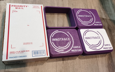
I attached a few convenience CAD models to the archive and updated it. Those files are 3D printed cases for shipping the controllers so if you do a group purchase you can just 3D print those cases, pack the controllers into those cases and ship those all over the world to whoever participated in the group purchase or wants to have a controller


You also can find the CAD models here if you want to edit those for your needs


The files can be found in the folder "M620 CAN Simple Controller\Idividual Parts Footprints, Symbols, 3D CAD\Extra parts"

1786753180259.png

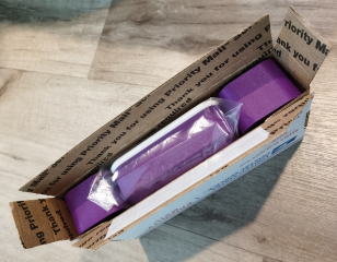
The case is designed to fit a USPS Priority Mail Flat Rate Small Box so you can ship the controllers convenient all over the USA for flat rate.

You can order USPS Priority Mail Flat Rate Small Boxes on the USPS website for free or grab those in your local USPS office for free.


1786754512069.png

3D Print the the controller case files "Case Cover_Rev2.step" and "Case Base_Rev2.step" (one of each per controller). Also 3D print one "Box Filler_Rev2.step" or two "Box Filler Halve.step" files (those are spacers to fill the empty space in the the USPS Priority Mail Flat Rate Small Box. The first one takes less 3D printing materials and two of the second one might be more secure for shipping, it is up to you which one to choose). I do not recommend you to use PLA for the case and spacers because of it might deform during the shipping in hot weather. I used PETG for those parts.

1786754918968.png

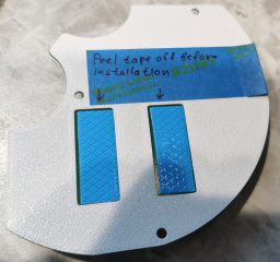
You also can flash the controller with the firmware and equip the controller with other 3D printed parts and fasteners like I did before shipping (install the insulation, the rotary encoder bumper, the thermal pads, the block terminals screws).

If you install the thermal pads keep the film on the bottom side of the pads so the person who will install it will peel it off before installation

1786755269959.png

Attach the controller to the Case Base with M3X5mm screws (the same screws you have to use to attach the controller to the M620 motor case). You also can attach the block terminals screws so the person who will receive it does not need to purchase those separately.

1786755466163.png

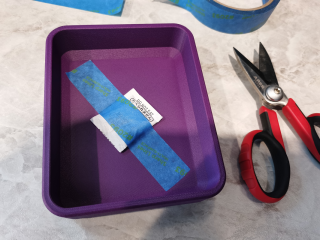
You also can tape a 1g bag of disenchant in the middle of the internal face of the Case Cover to avoid moisture condensation during the shipping.


1786755599159.png

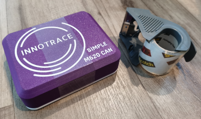
Close the case with the controller and tape it securely

1786756059950.png

You also can pack the case with the controller in a Ziploc quart bag to protect it from water

1786756150267.png

1786756207252.png

Fold the USPS Priority Mail Flat Rate Small Box

1786756381702.png

Put the case with controller and spacers onto the box

1786756468507.png

1786756550779.png

Peel the USPS Priority Mail Flat Rate Small Box adhesive protective tape off and close the box

1786756616747.png

Write your address and the recipient address, tape the box with extra packaging tape to secure it, make sure you collected money from the recipient for the controller, shipping and other parts. Visit your local USPS office, handle them the box, pay flat rate for the shipping and extra insurance if you need to, collect the receipt and provide the recipient with the package tracking number from the receipt.

1786756928335.png

And there you have it. One controller is locked and loaded and ready to be shipped. Someone, anyone? We need someone who is ready to dive deep into it, it will go just for materials and shipping cost.

1786757255824.png

Three more controllers may follow

1786757332515.png
 
Last edited:
We did it, guys! Thanks to @freesky01 for managing it for us. The new no jerk (no impact wrench) effect on throttle smooth firmware is here. The throttle duty cycle mode and PAS work together in this firmware.

You need to apply the "freesky_vesc_appconf 2.xml" App configuration file with VESC Tool application after flashing the firmware and make sure the ADC-->General-->Control Type is set to Duty Cycle

1787260146765.png


So if you are happy with this firmware please thank @freesky01 for this

freesky01 tested this on his INNOTRACE M620 controller he soldered (the 2 PCBs one) with 72V 100A battery and I tested this firmware on the INNOTRACE M620 Simple controller with 52V 80A battery. I guess it works good for him with INNOTRACE M620 controller and 72V but here are some notes about how it worked with INNOTRACE M620 Simple controller with 52V when I tested it.

It works good, but it certainly works different comparing with the original firmware.

First of all I experienced this firmware might cause Error 30 on display after turning it on. Usually you can turn the display off and turn it on again after 10-30 seconds and it starts working normally. I never experienced such issue on the original firmware. I even flashed the original firmware back and the display works without issues again. Then I flashed the new firmware and Error 30 on display can happen again. @freesky01 did not experience this issue though. But if you will experience it, don't panic, turn the display off and turn it on again after 10-30 seconds (you might need to do it a few times) and after this the display should start working. Maybe it is related to how PAS and throttle work was realized in this firmware. Or maybe this is related to this issue @marcos reported


I like the throttle, it engages with the drivetrain nice and smooth. No more impact wrench effect from stand still on loose drivetrain. It looks like I can achieve the full power with throttle.

The pedal assist also works smoother when it engages with the drivetrain and I like it. But for some reason it does not provide full power even at the highest assist mode. I can pull wheelie at Sport mode with the original firmware (which is medium support level), but on this new firmware I can not pull wheelie even on maximum support level. I did increase the throttle ramp time in VESC Tool and I do not know if the throttle ramp time affects the pedal assist, maybe pedal assist behaves like that because of I set large throttle ramp time and the firmware algorithm maybe emulates pedal assist using the throttle function somehow. The original firmware pedal assist feels more linear and powerful (even it can be harsh on drivetrain and abrupt from standstill, but I got used to it).

I also found if I pedal and then apply throttle without stopping pedaling it drops the pedal assist support to 0 and starts the throttle ramping sequence from 0 to the power the throttle demands. It is not a big deal but it would probably be nice if the throttle would pick the pedal assist power and ramped from that power level rather than drop it to 0 and ramped from 0.

I would say it will work good for commute and probably for eMTB, or for someone who does not like the harshness of the original firmware and does not need full power for pedal assist mode or someone who likes to use more throttle instead of pedals.
 
Last edited:
Back
Top