Lebowski
10 MW
Futterama said:Lebowski, I did autocomplete most of it since I still don't understand every setting. But I also did go through the whole menu structure right after I got the brainboard working, so there should not be any unconfigured entries in there except maybe for those that are not user-accessible. But I just got it running last night, and I was happy, posted it and went to bed. I will have more time tonight to play with the settings.
Regarding the current sensor settings, I did set option a-d in menu b and autocompleted option f-m along with autocomplete in menu f.
Regarding option d in menu i (perform FOC measurement) why would it need the battery voltage entered when it can measure it from pin 6? Pin 6 measurement is perhaps not the actual voltage but a change in voltage or how does that work?
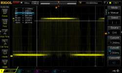
I will post a closeup of the brainboard tonight. Yes, it's a Lebowski style low inductance output stage using 0.04mm kapton tape as busbar seperator. I did not try more than have the motor running so I don't know the phase currents during the test. The brain was set to 10A phase current limit. The motor ran kind of unstable with varying RPM, and the voltage would have depended a lot on current draw since I used a current limiting resistor from lab supply to output stage. I tried to remove the resistor as everything seemed to be connected right, but something would trigger the overcurrent/overload protection on the lab supply when I applied throttle.
Yep, pin 6 only measures the change in voltage. The chip doesn't know the voltage as it doesn't know the resistor (voltage divide) ratio at pin 6. It doesn''t need to know
this to run correctly in FOC, the entered battery voltage is only used to calculate the inductance from the measurement data.
Maybe the lab supply tripped because the max battery current (menu b opt c) was set too high ? I would stay here a bit below the actual capability of the supply
as the calculation is not 100% accurate (it can be a few % off) and also depends on how the actual spec of the current sensors (these can also be a few % off). And,
the conductive foam won't help either... Njay is right about regen. When you close the throttle on a fast spinning motor a tiny bit of regen is unavoidable, this due
to current sensor mismatch and offset. I've seen my 65V supply displaying 100V on it's output meters, very scary. An appropriate (car)lightbulb across the lab supply will fix this. Not an issue with battery supply but the reason why I would NEVER put a diode in the battery line.
About running at varying rpm, the throttle is a torque throttle, so if motor friction goes up for whatever reason (grain of sand in bearing) rpm's go down and vica versa. This
is especially noticable in an unloaded RC motor not running at full speed.