torque arm picture thread

Chalo said:
calab said:
Chalo sir, Austin'ite what is the torque arms you use?
Grintechs?

I prefer Grin, but the time lag getting them means I often use something not so good, or make something from scratch. I have free access to a vertical mill, so that's my first resort when cooking up my own torque arm.

When a TA has some free play, and when the hub motor has an overrunning clutch or at least doesn't have regen or e-braking, I rotate the TA all the way in the same direction as the wheel's rotation before fixing it down. That way the axle doesn't have room to turn (opposite the wheel's rotation) before it gets resistance from the torque arm.
Amazon solves the time lag and the goofy shipping costs from CA.
 
Chalo said:
To me it looks like ... the use of stainless steel which is easier to bend than most regular steels, suggest.

Lol. That is funny.


Modulus of Elasticity 193 GPa 28000 ksi
AISI Type 316 Stainless Steel, annealed sheet

Modulus of Elasticity 29,000 ksi 200 GPa
A36 Steel

Such a big difference. A solid 3.5% difference in the modulus of elasticity.

Bahahaha. Bends so much easier... like butter... oh yeah that wont work ( sarcasm).

Steel? For that rusty 7 gPa ( giga pascals) extra, I guess that makes SO much of a difference. 193 giga vs 200 giga...


That is, if it's really a solution. For you see, not having your tork arms rust... might be valued.

7/200GPa differences. 3.5%. Negligible, and worth it for having a rust free bicycle.

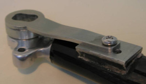
IMO, Chal. The ( mechanical structural design ) problem with THIS dropout ( IMO)( the laser cut stainless one... ) is that it allows a degree of freedom downward... and at the same time uses a nut on an aluminum / steel mooring sandwich.... and when you clamp a loaded aluminum thing ( bike ) on a traction creating driving thing ( the motor) the forces want to push them apart.... and the aluminum to steel interface will be the weak spot and allow a " sliding " of the alu/steel interface and release the axle in the dropout. Hopefully the chainstays handle the load, but Imade sure to use both the chainstay AND the seat stay, to handle the load,when I built my bolt on wheel mooring relocation.

Yeah like you said, they ( the tork arm maker) also have the opportunity to completely wrap the axle with steel.... bolt on, easy on and off for tire changes, and 360^ metal around the axle. That, plus a few tabs, less freedom to move. A double D cutout hole, not a slot.

A few well placed steel tabs could prevent this degree of freedom in the downward direction.

I blew my tire at 55mph and slid to a stop in about 100 yards, flapping my tire around in my home-welded aluminum 15lb bicycle frame.. dam violent. Old man ( in the car trying to pass me ) who saw the blowout was white as a ghost. 8 holes int he tube. Stainless took it without blinking.
 
amberwolf said:
New Clamping / Pinching dropouts on SB Cruiser, partial crosspost to leave the info here for anyone needing a similar thing:
https://endless-sphere.com/forums/viewtopic.php?f=2&t=67833&p=1737527#p1737527
BTW, this is what the dropouts originally looked like and how they were made, before I turned them into the first version of the clamping ones because even steel this thick wasn't sufficient by itself
https://endless-sphere.com/forums/viewtopic.php?f=2&t=67833&p=1050001&hilit=windings#p1050001

file.php
 
DogDipstick said:
Chalo said:
To me it looks like ... the use of stainless steel which is easier to bend than most regular steels

Lol. That is funny.

Modulus of Elasticity 193 GPa 28000 ksi
AISI Type 316 Stainless Steel, annealed sheet

Modulus of Elasticity 29,000 ksi 200 GPa
A36 Steel

Such a big difference. A solid 3.5% difference in the modulus of elasticity.

Hi!

Modulus of elasticity isn't yield strength. It's only stiffness, which is almost equal among all steels.

304L stainless steel plate has a minimum tensile strength of 70 ksi and a yield strength at 0.2% of 25 ksi.

(304L was the most common stainless steel alloy I encountered and worked with during my career as a machinist.)

Also, A36 is what fenceposts and filing cabinets are made of, and maybe not a first choice for what is essentially tooling. Let's look at some other, more appropriate and non-exotic options. These are data I snipped from various search results on the web. I made sure not to include heat treated conditions, because 300 series stainless steel can't be heat treated:

1144 steel
Ultimate Tensile Strength 108000 ksi
Yield Tensile Strength 89900 ksi

4130 steel
Tensile Strength, Ultimate 97200 psi
Tensile Strength, Yield 63100 psi

4140 steel
Tensile strength 95000 psi
Yield strength 60200 psi

12L14 free machining leaded steel
Tensile Strength 78 ksi
Yield Strength 60 ksi

Note that even the easy-to-machine option of carbon steel alloy is more than twice as strong as the typical stainless alloy.

When Endless Sphere's own Doctorbass manufactured open slot torque plates, he used QT100 (A514) steel in 10mm thickness. That alloy has a yield strength of 100,000 psi.
 
DogDipstick's design is the best. A dropout style TA requires high precision such as +/-.05mm or even .05mm total tolerance, but the DD 2-part clamp design can be made with wide open tolerances.

Motor axles are rarely within 10+.00/-.1 mm anyway as on the 205 print. It just depends on the power you push and whether regen braking is involved, and how much. I made a laser cut TA for 205-motored mopeds that measured 9.98mm flats on the small side of the kerf, in 304sst, worked out fine. But most of those people were pushing no more than 10kw or so, maybe 1kw 2-wire regen at most. For high power a clamper of any design is necessary.
 
chuyskywalker said:
I'm planning a torque arm extension for my Fiido Q1S scooter and looking for any feedback on the design before I start making chips on the CNC.

I did end up making this one, and had a batch made -- sold just about all of them now.

I was looking into making another set, but the cost to have these produced was...pretty high. What is really boiled down to was the 5-axis complexity of the manufacturing.

With that in mind, I really wanted to find a way to make a toruqe arm that could clamp, but also be made with 2d manufacturing.

I recalled seeing this video from Grin where they showed off an early version of their clamping torque arm with a cam for creating that "pinch" you need. That looks promising! Inspired, I looked around and found this cam'ing m5 bolt and did up a design which consists of the main extension arm and uses a flat piece, with the cam, to pull the dropout tight.

2023-01-12 13_30_03-Autodesk Fusion 360 (Personal - Not for Commercial Use).png

(You screw the cam in most of the way, back it off a bit, tighten the far bolt, lightly install in the middle bolt to keep things flat, tighten up the cam drawing the dropout tight, and then lock in the middle bolt.)

I went ahead and 3D printed this as an experiment (including the cam bolt, heh) and it does actually clamp:

cam-results.jpg

Think it'll work?
 
Could work if the cam screw can exert enough force to securely clamp the axle. Meaning can turning the cam screw end up pinching the axle with enough force? And can the locking screws hold the plate without slippage?
 
chuyskywalker said:
Think it'll work?

It probably will, but not much safety factor.

If you are laser cutting, why not do something like this?

You have a tension bolt laying on top of the main plate, then a square nut (or 2) that rests in a slot cut for it in the main plate. Then a plate around the outline of the bolt, then a 2-3mm top cover plate over the whole thing. Some smaller bolts strategically placed holding it all together.

You just need one high quality bolt that will be in tension, everything else will be handling light duty.

Screen Shot 2023-01-12 at 7.12.20 PM.png
 
Comrade said:
If you are laser cutting, why not do something like this?

You have a tension bolt laying on top of the main plate, then a square nut (or 2) that rests in a slot cut for it in the main plate. Then a plate around the outline of the bolt, then a 2-3mm top cover plate over the whole thing. Some smaller bolts strategically placed holding it all together.

You just need one high quality bolt that will be in tension, everything else will be handling light duty.

I think I see what you're saying, and dang that's likely a lot simpler than where I'm at, I'll rework. Thanks!
 
Or even simpler, if you know how to tap, you could cut two rectangular holes in the main plate, then cut out 2 small pieces that would fit through those holes perpendicular to the main plate. These small pieces would have holes for an M6 on both sides, so your tensioning forces do not distort the main plate. It would pull the main plate together using 2 bolts on each side. I guess you could use regular nuts too, instead of tapping, if you cut the main plate in the right place.

With laser cutting, your imagination is the only limit.

Screen Shot 2023-01-12 at 10.03.25 PM.png
 
Comrade said:
Something along these lines. I'm not much of a 3D modeler.

Screen Shot 2023-01-12 at 10.22.45 PM.png

I see what you're getting at, there's a lack of room on the rear of the plate, but here's something towards what you were talking about I think:

parts.gif
 
chuyskywalker said:
but here's something towards what you were talking about I think

Spot on! :thumb:

edit: if I was that good with CAD I'd try to redesign it around a thin plate -- thick plate -- thin plate design. Where the main tension bolt goes through the thick middle plate, without any twisting forces. Just the perfectionist inside me. But with the axle bolt torqued down, it should be fine as is.
 
chuyskywalker said:
I see what you're getting at, there's a lack of room on the rear of the plate, but here's something towards what you were talking about I think:
file.gif
parts.gif
That's nice--it could even be made from scrap metal with a hacksaw, drill, and files for the resource-poor / patience-rich. ;) (without a tap to thread the holes, nuts with bolts could be used to secure the plates together)
 
Comrade said:
edit: if I was that good with CAD I'd try to redesign it around a thin plate -- thick plate -- thin plate design. Where the main tension bolt goes through the thick middle plate, without any twisting forces. Just the perfectionist inside me. But with the axle bolt torqued down, it should be fine as is.

Pre-edit I was thinking about just that, based on your earlier statement. I started here:

2023-01-12 22_29_25-Autodesk Fusion 360 (Personal - Not for Commercial Use).png

But I really didn't like that the bolt head is only really torqueing on the edge of the actual extension, the remainder resting on "thins" and the random dangly bit at the bottom.

So I figured, why not capture both sides like the square nut, just give the bolt head more room so you can get a tool in there:

2023-01-12 22_30_23-Autodesk Fusion 360 (Personal - Not for Commercial Use).png

(With, maybe, less thing plate fixings, lol)
 
chuyskywalker said:
So I figured, why not capture both sides like the square nut, just give the bolt head more room so you can get a tool in there:

2023-01-12 22_30_23-Autodesk Fusion 360 (Personal - Not for Commercial Use).png
2023-01-12%2022_30_23-Autodesk%20Fusion%20360%20(Personal%20-%20Not%20for%20Commercial%20Use)[1].png
(With, maybe, less thing plate fixings, lol)

Is there room enough to slide the bolt out of the way of the axle so it can come out of the dropouts, without taking the thin outer plates off?
 
amberwolf said:
Is there room enough to slide the bolt out of the way of the axle so it can come out of the dropouts, without taking the thin outer plates off?

In a more optimized version of this design, that'd be a great idea. As noted by the absurd 16 bolts this needs a good deal more revision ;D
 
chuyskywalker said:
amberwolf said:
Is there room enough to slide the bolt out of the way of the axle so it can come out of the dropouts, without taking the thin outer plates off?

In a more optimized version of this design, that'd be a great idea. As noted by the absurd 16 bolts this needs a good deal more revision ;D

Substitute plug welds and it would be somewhat less absurd.
 
I'd replace the third pair of bolts, next to the tension bolt head, with a cut out to fit a rectangular "washer" made from the same thickness and type metal as the middle plate. It would distribute the forces from the tension bolt head much better than a thin washer.

file.php
 
Chalo said:
Substitute plug welds and it would be somewhat less absurd.

Fair; but that's a whole 'nother level of making I've not gotten into yet.

amberwolf said:
Is there room enough to slide the bolt out of the way of the axle so it can come out of the dropouts, without taking the thin outer plates off?

Yes, yes there can be:
2023-01-13 09_34_35-Autodesk Fusion 360 (Personal - Not for Commercial Use).png
 
chuyskywalker said:
Chalo said:
Substitute plug welds and it would be somewhat less absurd.

Fair; but that's a whole 'nother level of making I've not gotten into yet.

amberwolf said:
Is there room enough to slide the bolt out of the way of the axle so it can come out of the dropouts, without taking the thin outer plates off?

Yes, yes there can be:
2023-01-13 09_34_35-Autodesk Fusion 360 (Personal - Not for Commercial Use).png

Looks like you need more clearance to give the hex wrench enough room to loosen and remove the bolt so you can get the wheel off.
 
The last iteration with the reversed bolt looks significantly less robust than the previous design. And more difficult to use.

This design with a solid plate under the tension bolt head looks stronger. But in the end, it's your torque arm. :lol:

Screen Shot 2023-01-13 at 2.27.10 PM.png
 
Comrade said:
The last iteration with the reversed bolt looks significantly less robust than the previous design. And more difficult to use.

This design with a solid plate under the tension bolt head looks stronger. But in the end, it's your torque arm. :lol:

Your feedback is totally valid and useful, I appreciate it. I rolled with that idea a bit, added some little wings to it to keep the "plate" washer a bit more in place. I also like that this setup gives a much tighter, round surface for the hex head to sit on. And, of course, way easier access to the bolt as well.

rear-washer-plate-clamp.gif

edit: can also be mirrored which is advantageous in being easier to hand manufacture, but also you don't need super great tolerances to get the square nut to be effective and you can now use better nuts (like here, a flanged nylock) and be able to tighten from two sources.

2023-01-13 13_06_43-Autodesk Fusion 360 (Personal - Not for Commercial Use).png
 
Back
Top