• Howdy! we're looking for donations to finish custom knowledgebase software for this forum. Please see our Funding drive thread

APL's DIY axial-flux motor

Yep, I tried to make them work every way I could, but have to start over, and get some more wire length. No easy way
out other than machining the plate OD, but I don't really want to do that either, because the pins and glue may cause
problems, and I don't want to go backwards with all that work.

It's a set back, but not a big one,.. rewinding the coils isn't too hard, just time consuming. My bad.
 
I'm going to try to round off the edge of the plate a little more, to help with insulation, but this titanium is the
toughest darn stuff!

I've been thinking about the bearings again too,.. it was suggested before that I use tapered roller bearings instead of
the ball bearings that are in there now. I was reassured that the ball bearings were sufficient, but the more I think of
it, the more I have to wonder.

I think that most of the axial's that I've seen use rollers. And the ball bearing was never intended to be used in axial
loads, which sometimes reach 300+ lb. magnet strength. Although, once the motor is together, it should be even.

Still, just in case the problem this motor is having is two fold, weak stator plate, and side loaded bearings, I decided
that it might be worth taking a look at some tapered bearings to see if I could find a match.

As luck would have it, there is a pair of rollers that will fit perfectly ID and OD, with the exception of being slightly
wider by a few millimeters. I should be able to turn a little more clearance for them in the axle and caps, and may
even be able to eliminate any shims.
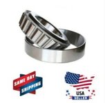
Tapered roller bearings..jpg

Another advantage to using tapered rollers is that they come directly apart, so theres no 'pulling' the bearings off of
a press fit, when taking the motor apart,.. the two sides stay in place, and can even be bonded there.

They're cheap enough, so I ordered a pair out, and we'll see how all that pans out when they get here. I might have to
remake the non-drive bearing cap, but that one is pretty wimpy anyway, and always needed to be redone.
 
I'm not sure they are needed in this case. They actually might cause other issues. Those bearings are build to be mounted preloaded, if they are not there is play and it can't be adjusted.
As discussed before once the two halfs are resting on the spacers no magnet axial load are taken by the bearings assuming the functionnal play is good on the axle ( some 1/10 of a mm is good enough with a 1 mm airgap)

Envoyé de mon Redmi Note 9S en utilisant Tapatalk

 
Thecoco974 said:
As discussed before once the two halfs are resting on the spacers no magnet axial load are taken by the bearings assuming the functionnal play is good on the axle ( some 1/10 of a mm is good enough with a 1 mm airgap)

Exactly. A tiny gap between sidecovers and spacer to preload the bearing when assembled should be enough to remove axial play. Thats how it is done on most hubmotors (if sidecover screws are loose there usually appears a gap).
 
Ok, well, I guess I'll set them aside as an option,.. at least they will be on hand should the need arise to use them.
The cost was minimal, and I was surprised to find a pair that would interchange.

No need to complicate things for now, and I'll just stay on course with the stator build. I have plenty of other tasks to
complete on that. Thanks for the input! :thumb:
 
Progress is slow because the heavy wire doesn't rewind very well, and makes the clearance's too tight. The cores could
use a few more mm's off of each side for 14 awg wire. 15 awg wire would have been a better fit for this motor.

Got off to a rough start, but it started getting easier, and now it just about done. The winds are a little rougher than
before though, and I had to run one coil wire over the top to get it to fit, but it will work.

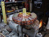
Stator assembly..jpg

The spacers need clearancing for the larger OD plate and crossover wires, so I did it the hard way with a plunge cut
and belt sand. (I don't really trust the lathe fixture I have for it.) Not a looker, but done, safe, and move'n on. :thumb:

Spacer clearance.jpg

So next up will be connecting all the wires. :)
 
Looking great so far!

Hooking up all the wires is the part I hate the most. More than once I messed up something and had to tear apart and redo a whole motor. Just keep careful track of where things are supposed to go.
 
Yep, getting close. My worry at the moment is with the SMC shorting out the fingers. I know we talked about it,
and determined that it won't be a problem,.. but it still makes me feel uneasy. :confused:

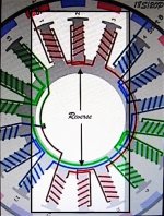
The wiring is relatively simple, with two sets of three coils, and the middle coils reversed. So it's pretty easy to keep
track of on this motor. Lots of room for wires this time too, so it's moving right along.

IMG_2517 copy.jpg

The part I don't like the most, is getting the stator centered, and adjusting the air gaps. Taking it apart and back together
a few times gets old fast.

Well, the coils are in, and the wiring is almost done. So the air gaps are next, and once I spin it by hand I'll know how the
slots are working out.
 
Wiring is finally done except for the phase wires and some wire ties. Lesson learned from last time is to keep the wire
to the outside, and leave the middle open.

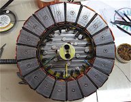
Look'n like a motor now. 8)

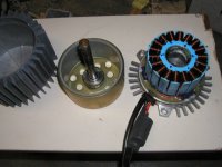
V2 stator ready..jpg

Next is the dreaded rotor adjustment. But on the good side,we get to find out how the Ti plate works,.. and if this thing
is going to pull some watts, and do some work around here for a change! :)
 
That thing should be a beast.

Below is my old BMC scooter motor that's tiny by comparison. It could do 5kW peaks and pull 2.5kW for pretty long hills.
The stator is about 4" in diameter. It uses the same concentrated pole winding arrangement as yours.

BMC 600w motor apart 2.jpg
 
That's a beautiful motor,.. so simple! I'm beginning to have a new respect for radials. I'm surprised to see how thin the
back iron is. But yea, smaller by comparison, and higher in rpm's,.. that's still an amazing output for a 4" motor! :thumb:
This one should be a real stump puller if I can get it fired up. :)

I checked out McMasters for bearing shim washers,.. I don't know why I didn't look earlier,.. but of course, they have
every kind of washer made, english or metric sizes. (Duh)

So I ordered out some 1mm and .3mm thick shims for each bearing, which should make adjusting the gaps less of a chore.

I'm starting to get pumped,.. and even thinking about the 'ride' test again, although, it's going to be below zero this
weekend, so I'll probably have to wait on that. :wink:
 
APL said:
Yep, getting close. My worry at the moment is with the SMC shorting out the fingers. I know we talked about it,
and determined that it won't be a problem,.. but it still makes me feel uneasy. :confused:

The wiring is relatively simple, with two sets of three coils, and the middle coils reversed. So it's pretty easy to keep
track of on this motor. Lots of room for wires this time too, so it's moving right along.

IMG_2517 copy.jpg

The part I don't like the most, is getting the stator centered, and adjusting the air gaps. Taking it apart and back together
a few times gets old fast.

Well, the coils are in, and the wiring is almost done. So the air gaps are next, and once I spin it by hand I'll know how the
slots are working out.


Thanks for that, I was having trouble envisioning how the winding scheme worked.
 
I guess I should point out that my little BMC motor had a big blower pushing air through the stator. No way it could handle that much power without it. Stock version of it was rated for 600W. Still pretty peppy for such a little motor.

Your axial motor has a lot more heat mass, so you can really push it hard for short bursts assuming the deflection issue is resolved.
 
The narrowness of the tooth, and corresponding long brim lengths, are striking,.. very low steel and copper mass.
It would be hard to imagine a lighter weight per power motor.

I tried looking up the motor on Images, but didn't see any internal photos, is this after modifications?
 
The picture I posted was the before picture.
The magnets aren’t the strongest but that helps the iron losses.
 
Wirings done, and I added a few drops of glue and zip ties here and there, plus, I added a wire to the Wye connection
so I can measure the single phase voltage outputs. Added some Locktite and final torque to the core screws,.. so
she's all ready for eddy.

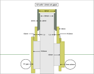
In order to picture whats going on with the air gap spacing, I took as many measurements as I could, and then created
a 2D drawing in Cad. It really helps to see what kind of shim's I'll need, and how much to mill off the spacers.

V2 Shim specs. 1.5 mm gaps..png

I decided to start out with 1.5mm gaps, to allow for small error's in measurements, rotor flex, and give me some wiggle
room. All I'll need to do is take 1mm off the 43mm spacers, and add a .3mm shim on the non drive, and a 1mm + .3mm
shim to the drive side. This should give me .3mm preload on each side. (.3mm is all I have at the moment)

That's the plan anyways, I'll finish up the spacers today, and should be able to get it put back together for a test fit.
If all goes well I'll be putting power to it this weekend. My little pellet stove doesn't keep up with single digit temps, so
shop time is iffy, but hopefully by Monday I can show some results. :thumb:
 
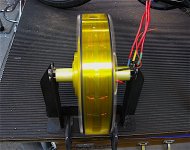
Good, good, good! She's up and spinning again! The new stator plate is strong as an Ox, and all the slots are open. :thumb:
Drinks and cigars all around! 8)

V2 running, new stator plate..jpg

One of the spacers didn't seat in the mill vice, and I had to take another .5mm off of all of them to straighten it out,
but ay least I was able to save it. That brings the final air gaps to 1.25mm for now.

There are a few new problems I found though,.. one is that the magnets are not all exactly the same hight, some are
as much as .020" difference, or .5mm. Never noticed it before, but I can spin the rotors in the lathe and clean them up
next time I have it apart. Hopefully I can tweak it more towards 1mm gaps.

The other problem is with the CA, it's reading negative watts when the motor is not running, and I don't have a clue as
to why. Maybe the shunt is craping out? I've noticed that it's been acting up like that for a while, but now it seems to
be getting worse. I have another shunt that I can switch out. Any ideas?
When I measure the free spin, it reads 'less' Neg watts. (39.6v & -131w)

CA reading Neg..jpg

Next up, I'll get some Kv numbers, and of course the real test is the road test,.. but thats going to have to wait until
the weather gets a little better, in a week or so. :)
 
The negative watts just means that the CA sees reverse current flow, which means the shunt amps need to be zeroed in the ca menu for that.

If it keeps changing over time, you probably have a connection issue on the blue/white shunt +/- wires from the shunt to the CA. The voltage across these is very small, so a connection issue can cause a change in voltage that the CA sees vs what's acually across teh shunt by quite a bit.


BTW, I like your "transparent aluminum" ;) outer ring.


(I know...it's just cuz the motor is spinning, with the cooling gaps...but it *looks* transparent! ;)
 
That is cool isn't it? It's like X ray vision! Maybe I should put a strobe light inside.

Thanks amberwolf, you are wise indeed, I didn't know that it had a zero in on the menu, and the small shunt wires
sound likely to me too, I'll take a close look at what I have going on there. :thumb:
 
Yay! That's so great to finally see this beautiful motor running!!!!
Super happy for you.

I can't wait to see how powerful it actually is, I'm pretty sure it'll be great.
Bravo!
 
That must have felt great seeing it run :thumb:
I've been following this thread from the beginning an really enjoy every step. Will stick around to EVentually see it propel a bike 8)
 
Awesome!

I don't think you will have good results trying to grind the surface of the magnets. Just stay with the bigger gap.

Some LEDs with resistors across the phase wires on the stator will be a simple way to make it glow on the inside.
 
Back
Top