Futterama's power stage for Lebowski's controller IC

Here is a shot of the high-side gate-source and also the source-drain. I have a low side pulse to charge the bootstrap capacitor before firing the high-side. I programmed a pretty big deadtime of 100µs just to make sure.
When scoping the high-side, I have to disconnect everything else, all the other scope channels and even the lab supply, so I only have the gate-source signal. I don't have isolated or differential probes.
 

Attachments

  • gate-source.png
    gate-source.png
    12.3 KB · Views: 2,244
  • source-drain.png
    source-drain.png
    12.4 KB · Views: 2,244
So I finally got around to making a new gate driver PCB from the 0.5mm double sided PCB material. I added schottky diodes for turn-off and I just started with 7.5­Ω resistor so I have 15Ω ON resistance and 7.5Ω OFF resistance. I also kept all components on one side of the board though I added an extra bypass capacitor for the gate driver IC on the bottom anyway.
I only soldered the low-side just for test.

Yellow trace is drain-source, blue trace is gate driver input in the first shot and gate-source in the rest.

What I find disturbing is the 300ns it takes to discharge the MOSFET gate to the gate threshold or miller plateau. It is very clear that the discharging all the way from 12V takes a long time compared to the time it takes to actually turn off the MOSFET (200ns) after the miller plateau is reached. It's 500ns combined and add the gate driver delay to this also.

Is it just a matter of using a lower OFF resistance?
 

Attachments

  • DSCF3500.jpg
    DSCF3500.jpg
    47.3 KB · Views: 2,192
  • DSCF3499.jpg
    DSCF3499.jpg
    42.7 KB · Views: 2,192
  • DS1Z_QucikPrint7.png
    DS1Z_QucikPrint7.png
    13.6 KB · Views: 2,192
  • DS1Z_QucikPrint8.png
    DS1Z_QucikPrint8.png
    14.4 KB · Views: 2,192
  • DS1Z_QucikPrint9.png
    DS1Z_QucikPrint9.png
    12.8 KB · Views: 2,192
Futterama said:
zombiess said:
I am puzzled as to why your current turn off is so slow.
Well, it actually makes good sense to me when looking at the gate-source shots. The MOSFETs gate-source threshold is around 2.3V. It does not take as long to charge the gate from 0V to the threshold of 2.3V, as it takes to discharge the gate from the 12V down to the threshold.
You answered your own question above...
 
I can actually reduce the turn-off time with ~100ns just by using 8V gate drive instead of 12V.

Here is a shot using 8V gate drive. The ringing in the end is worse in this shot, but that is only because I increased the pulse length to 33µs to get a more realistic view (longer pulse, higher current in the connected test coil).
 

Attachments

  • DS1Z_QucikPrint8.png
    DS1Z_QucikPrint8.png
    12.7 KB · Views: 2,187
100µs pulse, 12V gate drive, 11.1Ω ON resistance, 3.9Ω OFF resistance + diode forward voltage drop of 300mv.
Around 100ns turn-on time and 300ns turn-off time.
 

Attachments

  • DS1Z_QucikPrint2.png
    DS1Z_QucikPrint2.png
    12.3 KB · Views: 2,161
  • DS1Z_QucikPrint1.png
    DS1Z_QucikPrint1.png
    13.4 KB · Views: 2,161
I'm pretty sure I don't need the MOSFETs to switch this fast, I'm just looking for limits. I have no idea of the inductance of my RC car motor, so this is just a small test to see how high I can go with the PWM frequency.
I recently came across a website with Lehner motors for RC use. They recommend 8-10kHz switching frequency for their motors. So perhaps that is in the ballpark for my motor too.

From what I remember reading in other threads, the deadtime should not exceed 5% of the switching period. With 10kHz, the switching period is 100µs. 5% is then 5µs. So a MOSFET switching time of 1µs would be ok for 10kHz operation?
 
I don't consider those initial 300ns until the Miller plateau to be part of the MOSFET switching time, they are at most, latency. Reduce gate voltage or reduce gate resistor is very different. In the 1st you reduce latency; in the 2nd you reduce latency and switching time, with the increase in di/dt and its known consequences.

My opinion is that we should push for low latency, because that allows us to reduce dead time. Beside the "waveform distortion" issue HH talks about, during dead time we have the MOSFET body diodes conducting, which dissipate a lot of heat.

In this shot
file.php


see how the voltage doesn't go back right away to Vbat at the end? You're either pushing too much current or not having enough capacitance at the power input, it seems to be ringing hard.
 
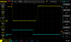
Njay, thanks for commenting. You are right, the switching time must be from the MOSFET starts to turn off, till it is finished, not from when the gate driver IC wants it to turn off.
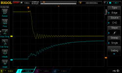
So I have a big delay/latency compared to the actual switching time due to the "high" gate drive voltage. I can lower this voltage but it will increase RdsON and also increase the turn-on time. But maybe 12V is not optimal, maybe it doesn't provide the best balance between turn-on/off times and RdsON that makes the controller most efficient (lowest losses).
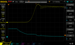
As far as I know, the deadtime has a big impact on the efficiency, as you just said, the body diode is conducting during this time and it will dissipate a lot of heat, probably a lot more than what a little higher RdsON will dissipate.

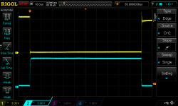
For some reason I would like to see identical turn-on and turn-off delay/switching times, but is there any reason for this, other than it looks nice on the scope?

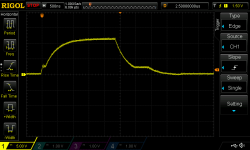
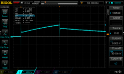
Regarding Vbat, yes I noticed that, and was also thinking I would take a look at the waveform after turn-off but didn't get to it before I forgot about it again.
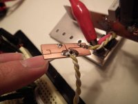
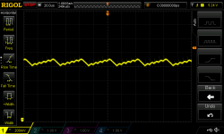
I have 2x1000µF aluminium caps, but they are just the best I had, the ripple current is not very high, some 1.7A with 42mΩ impedance, 25V. I'll get better caps when I order components again but now that I look at my notes about caps, the ones I had my eye on, are 50V, 2200µF, 3.7A ripple, 20mΩ ESR and I was planning to use only one of them:
http://www.digikey.dk/product-detail/en/EGPA500ELL222ML40S/565-3401-ND/3528551
But still, I don't know how much current I put out, the current sensors are one of the things I need to include in my order :lol:
 
Oh! The Vbat issue is solved. I'm powering the thing from my lab supply, but earlier today I fried 2 of my probe ground springs because I somehow shorted them to the + supply and they got hot glowing yellow :shock: so I added a 4Ω resistor from the lab supply to the input caps for protection. Without this resistor, the scope shot looks better.
 

Attachments

  • DS1Z_QucikPrint11.png
    DS1Z_QucikPrint11.png
    13.6 KB · Views: 2,138
I did a little test to get a ballpark number of the current in my 100µs pulse. I added a shunt resistance (just a piece of thin solid copper wire) in series with the coil and measured the voltage drop across it while applying a known current (3.9A and measured 12.5mV) and then again with the pulse from the MOSFET. I disconnected the lab supply before connecting the scope to avoid shorting anything again, so all the current is from the capacitors.
The voltage drop across the shunt during the pulse, reaches 304mV as seen in the scope shot.
According to my calculations: 12.5mV is 3.9A, so 304mV/12.5mV = 24.32 * 3.9A = ~95A :shock:
 

Attachments

  • DS1Z_QucikPrint2.png
    DS1Z_QucikPrint2.png
    14.6 KB · Views: 2,135
My lab supply was set to 16V. So I just took some scope shots with 5S LiPo measuring 18.9V. I was thinking the power of the LiPo cells (5000mAh, rated 20C continuous, 30C burst) could change the game a bit.
At least, the current got up to 138A according to my shunt setup :lol:

Shunt measurement:
5S_LiPo.png

100µs pulse, "extended" view so we can see there is no Vbus voltage sag or heavy ringing long time after turn-off. But there is this higher than bus voltage just after turn-off and the drop in voltage back to Vbus, 700µs after turn-off. I guess this is the forward voltage of the high-side body diode, conducting the back-EMF pulse from the coil. Am I correct?
View attachment 2

Turn-on.
View attachment 1

Turn-off. I actually added a 15nF cap to gate-source like zombiess did, but I don't see the same big effect on the ringing as he did. But I don't have 2x bus voltage spike after turn-off either. The ringing is only 5V above Vbus.
DS1Z_QucikPrint4.png
 
Futterama said:
But there is this higher than bus voltage just after turn-off and the drop in voltage back to Vbus, 700µs after turn-off. I guess this is the forward voltage of the high-side body diode, conducting the back-EMF pulse from the coil. Am I correct?
I would say yes! It's easy to see with a low supply voltage, once you go up it's a small difference on top of a high value and you stop being able to see it.
 
So my recent order from Digikey was put to use when I built the PCB for the LTC3630A step-down regulator today.

The regulator works fine, the PCB does get a little warm at near full load but nothing alarming. The values I measured with a 10ohm power resistor as load was 490mA output at 4.99V with 99.7mA input at 30.5V (that's 31V from my lab supply and 0.5V drop over the input diode).
This calculates to 3.04085W input and 2.4451W output (excluding the input diode). That's 80.4% effeciency, a bit on the low side compared to the calculated 93%.
The ripple at full load was around the 120mV with 3x22µF output capacitors.

The PCB measures about 20x20mm.
 

Attachments

  • LTC3630A.jpg
    LTC3630A.jpg
    55 KB · Views: 1,974
  • output_ripple.png
    output_ripple.png
    12.6 KB · Views: 1,974
With much help from the country-local FAE from Linear, I have figured out why the efficiency is so low on my DC-DC converter. The inductors I got, have a high core loss, so I'll be getting some better with my next order from Digikey. Until then, I can use the ones I got.

I also got some FOD8332 isolated gate drivers from Fairchild. I know HighHopes says not to use gate drivers from Fairchild, but they are pin-compatible with the ACPL-333J which I'll be getting with my next Digikey order, so I can use the Fairchild devices to built my circuit and do some tests until I'm ready to order from Digikey again.
The reason I didn't order the ACPL-333J and isolated supplies with the recent order, was that I knew for sure I didn't get all the components just right the first time, so I wanted to save some of the expensive components for another order, to be sure to get the order value above $88 so I can get free shipping to Denmark :wink:
 
I sent a TQFP dsPIC device to Lebowski for programming with v.2.21, got it back, and had some problems making it work on my test board. I found that all the supply pins need to be connected, I think it was the AVDD/AVSS pins that needed to be powered for the chip to work at all. But now it works and I have already been going through the menus to do some initial setup.

Next step is to hook up some bootstrap gate drivers (those I already designed), a small powerstage and the current sensors, so I can get a motor running. A running motor will give me further motivation to get more work done on the isolated gate drivers, desat detection and the big output stage.
Also with the Lebowski chip at hand, I can work on getting the CAN bus running for throttle and reverse. I have no experience with CAN bus, so I'll have to read up on that part.
 
The motor is spinning! :D

It needs tweaking as the controller will short circuit the lab supply if I don't have my 4Ω safety resistor between the supply and output stage :lol:

The Lebowski v2.21 brain is on the small square PCB near the breadboard. On the breadboard I have my RS232 driver so the brain is connected to the PC COM port (you can also see my WiFi module on the right side of the breadboard). The LiPo below the breadboard is supplying the brainboard through a 7805 so it gets 5V. The other LiPo between the breadboard and the lab supply is supplying the bootstrapping gate drivers. The motor is mounted in the vise.

The brain will switch between drive_2 and drive_3 just fine. The voltage input to the FOC measurement is not connected yet. I haven't even measured motor inductance but it still runs. I just soldered everything up, and set the most basic parameters in the brain and there it goes 8)
 

Attachments

  • DSCF3563_s.jpg
    DSCF3563_s.jpg
    86.6 KB · Views: 1,630
  • DSCF3564_s.jpg
    DSCF3564_s.jpg
    88.9 KB · Views: 1,630
I don't know whether the current sensors are connected the right way around (giving a voltage higher than 2.5V when current is flowing from the output stage to the motor) so that might be the cause of short circuit without the safety resistor, but this will be all for tonight, I'll do tests and measurements tomorrow, and I'll give some scope shots when I can remove the safety resistor from the supply line.
 
Congrats! It's a big accomplishment just to get to this point.

BTW, I sure hope that is not anti static foam you have those current sensors sitting on, that type of foam is conductive.

I'm still plugging away trying to miniaturize the entire setup for a 200A controller which could be used for ebike/eskate/large scale R/C. I'm also working on a high current setup, 500A range. Low current is pretty easy, but miniaturization is difficult.
 
Cool, looking really good, good job!

Be carefull with power supplies and motor controller; power supplies tend to not sink any current so, if you do hard/semi hard deceleration, the voltage on the positive power bus can go up to unconfortable values. The regen current will have only the bus capacitors to go into, forcing them to raise the voltage. I don't know if it's an issue with Lewbowski's brain, he has it all well covered up, but with a simpler controller it is.
 
Hey congratulations !! Cool :D

Looking at the pictures the current sensors are the right way around. Did you just autocomplete the whole setup ? I hope you did at least the current sensor back to default
setting (offset and gain calibration are only necessary for HF). You really should do the FOC inductance measurement, only takes a few seconds and is really necessary, especially on a virgin chip where the default ROM contents is all 0xFFFF ...

can you post a closeup of the brainboard and gate driver board ? I see you're using the low inductance output stage ? How many phase-amps did you try ?
 
Thanks guys.

zombiess, yep, that's antistatic foam, I probably shouldn't run the controller sitting on it, well spotted :)

Njay, regen current is set to 0 as long as I'm using the lab supply. Also, it's a small unloaded motor which does not have much rotor inertia. But it is of course something important to be aware of.

Lebowski, I did autocomplete most of it since I still don't understand every setting. But I also did go through the whole menu structure right after I got the brainboard working, so there should not be any unconfigured entries in there except maybe for those that are not user-accessible. But I just got it running last night, and I was happy, posted it and went to bed. I will have more time tonight to play with the settings.
Regarding the current sensor settings, I did set option a-d in menu b and autocompleted option f-m along with autocomplete in menu f.
Regarding option d in menu i (perform FOC measurement) why would it need the battery voltage entered when it can measure it from pin 6? Pin 6 measurement is perhaps not the actual voltage but a change in voltage or how does that work?
I will post a closeup of the brainboard tonight. Yes, it's a Lebowski style low inductance output stage using 0.04mm kapton tape as busbar seperator. I did not try more than have the motor running so I don't know the phase currents during the test. The brain was set to 10A phase current limit. The motor ran kind of unstable with varying RPM, and the voltage would have depended a lot on current draw since I used a current limiting resistor from lab supply to output stage. I tried to remove the resistor as everything seemed to be connected right, but something would trigger the overcurrent/overload protection on the lab supply when I applied throttle.
 
Back
Top