jonescg's eCRX pre-build thread!

This thread started in 2012?!!! That's some long legs there.
None of my projects are as challenging as yours, but I worry about mine. Like if I am going to finish any of them before I myself finish.
Wish I had your shop.
 
I bought this car in 2012 with the intention of converting it to electric back then. I never did much to maintain the engine because I knew it would be coming out... 12 years later it finally came out. It's a combination of scope creep, employment, space, and available time. It's finally happening at least. It also doesn't help that I have a dozen projects on the go at point, plus client jobs, and my day job. And volunteering with AEVA...

Anywho...

New subframe is in and the power steering rack seems to bolt up where it's supposed to. I think.
It looks like a fairly forgiving fit, but I'm worried my alignment might not be ideal.
 

Attachments

  • PS remounted2.jpg
    PS remounted2.jpg
    147.8 KB · Views: 12
  • PS remounted1.jpg
    PS remounted1.jpg
    198.9 KB · Views: 12
So far so good. Last part of the subframe puzzle is the sway bar. I read it's not a big deal for the front, but in terms of getting this vehicle re-licensed I'll probably need a good explanation. In the event I can't leave it off, I might try and fabricate some pickups on the rear chassis mounts for the subframe. Basically a C - shaped bracket with a flat face I can mount the sway bar stays to.
 

Attachments

  • Sway bar mount5.jpg
    Sway bar mount5.jpg
    130.5 KB · Views: 5
  • Sway bar mount4.jpg
    Sway bar mount4.jpg
    123.6 KB · Views: 5
Little more progress on the motor mounts. Lots of cardboard aided design, followed by Sketchup made for an easy shopping list of laser cut 4 mm steel parts. I can weld these up with my stick welder no trouble. Hope to have these welded up by next weekend, and the Leaf motor mounted the weekend after! Driveshafts will be the next major headache.
 

Attachments

  • 20250103_154825.jpg
    20250103_154825.jpg
    95.3 KB · Views: 14
  • 20250103_112028.jpg
    20250103_112028.jpg
    86.1 KB · Views: 14
  • All motor mounts assembled.jpg
    All motor mounts assembled.jpg
    205 KB · Views: 14
  • All motor mounts thickness guide.jpg
    All motor mounts thickness guide.jpg
    97.1 KB · Views: 14
Ceramic heater core is bench tested and ready to be installed. 2.4 kW of instant heat!
 

Attachments

  • ceramic heater core fitted.jpg
    ceramic heater core fitted.jpg
    140.9 KB · Views: 11
  • ceramic heater core full power.jpg
    ceramic heater core full power.jpg
    59.7 KB · Views: 10
  • ceramic heater core fitted2.jpg
    ceramic heater core fitted2.jpg
    241.3 KB · Views: 10
Around here we call that stepping out of the shade. ;)
2.4 kW of heat in Perth in January is "Extremely unwelcome". Much more interested in getting the air-conditioning fitted for the first time since about 1998...
 
Much more interested in getting the air-conditioning fitted for the first time since about 1998...
Oh, I understand that!

When I still had Yogi and Kirin, who liked to go places with me, I had been working out the design for an air-conditioned "horse trailer" for the dogs, kluging together an inverter and batteries to run a window-A/C unit to keep an insulated "box" cool even in the worst summer heat. With just JellyBean, who doesn't go anywhere, there's not much incentive to finish that idea and build it, but "someday". :)

I'd also been considering putting that on the trike directly instead, and making a "collapsible"/removable enclosure for the rider area of the trike, connected to the doggie/cargo area in back, so I could benefit from it, too. ;) This version is more likely to happen, but still not very.


Late fall, and winter here, can get down into the 30s or 40s F for lows, but the sun comes up and brings that up with it pretty quick most of the time. The highs are usually in the high 60s or 70s, sometimes even the 80s, with occasional rare excursions up to the 90s F, for as much as ~50F variance between the high and low for a day. :/
 
Last edited:
Several modifications on the sway bar stays were required, like making it much shorter and re-locating the stay holes, but I got there in the end. It does a pretty tidy job of holding the bar up, and any torsion on the chassis as you round a corner will put vertical loads on the stays, which look to be well supported.
sway bar support1.jpg sway bar support modified.jpg
I've now moved onto the motor mounts, and while the right front mount is coming up good,the left front is well out to lunch 😕 
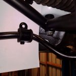
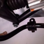
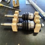
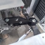
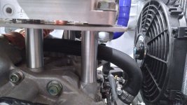
. Not only were two of the the holes in the wrong spot, it was way too short for doing anything useful with.
motor mounts to be welded1.jpg
I might get that one re-done, amongst other corrections.
 
Motor is mounted! Some grinding and paint for the welder I ain't left to be done, then I can start to think about the drive shafts.
 

Attachments

  • RHS front mount fab1.jpg
    RHS front mount fab1.jpg
    146.9 KB · Views: 14
  • LHS front mount fab1.jpg
    LHS front mount fab1.jpg
    166.5 KB · Views: 15
  • rear motor mount fab2.jpg
    rear motor mount fab2.jpg
    214.5 KB · Views: 15
  • RHS front mount fab2.jpg
    RHS front mount fab2.jpg
    170 KB · Views: 16
  • motor mounted1.jpg
    motor mounted1.jpg
    176.6 KB · Views: 15
Driveshafts next. I'm not planning on doing these myself, but I hope to slide the Honda shafts inside the Leaf shafts so I can determine the final length and mark it. Then I can take them to a driveshaft specialist and get them to work their magic. At this stage it's looking like a specialist weld job is the way to go, but they may offer a fully custom driveshaft build (at a significant cost).

The aftermarket CRX shafts are about 27.3 mm diameter, and the inside of the Leaf shaft is 26.5 mm diameter. So both probably need to be turned down and honed to accommodate each other.
 

Attachments

  • CRX Driveshafts cut.jpg
    CRX Driveshafts cut.jpg
    197.5 KB · Views: 6
  • Leaf LHS driveshaft cut.jpg
    Leaf LHS driveshaft cut.jpg
    246.6 KB · Views: 6
  • Leaf RHS driveshaft cut.jpg
    Leaf RHS driveshaft cut.jpg
    124.6 KB · Views: 6
driveshaft matchup.jpg
I took the shafts to a mate who has an enormous lathe, and he was able to bore the inside out of the Leaf shaft to a depth of about 110 mm from where I cut it off. The solid shaft needed to go deeper than that, so we just lopped 60 mm from the ends to be sure it wouldn't bottom out. There looks to be at least 80 mm of overlap there now.
driveshaft machined to fit.jpg
So, quick test-fit and we're ready to take these down to the driveshaft shop for slotting and TIG welding!
RHS DS test fit1.jpg LHD DS test fit1.jpg Motor and DS test fit top.jpg
 
Minor update - I installed the radiator and dropped another $500 on aircon parts.
I also pulled the central locking out since I never used it and put new speakers in the doors. Now all I need is a music playing device...
 

Attachments

  • 20250126_212333.jpg
    20250126_212333.jpg
    67.8 KB · Views: 7
  • 20250126_212437.jpg
    20250126_212437.jpg
    70 KB · Views: 7
Driveshafts are welded! Hope to install these on the weekend and tighten up all the suspension components.
 

Attachments

  • driveshafts welded.jpg
    driveshafts welded.jpg
    410.2 KB · Views: 9
And that was a fairly productive summer! I'll chip away at small stuff between now and the Easter holiday, but I hope to get much of the cabin back together by then... 😬
 
Driveshafts are welded!
Do you plan to drive this at low power or are you ready to blow your motor and/or inverter?
I mean, it's generally what happen when shaft broke at weld or just across weld.
That happen to me and my Smart 15 years ago, this happen to my boss with his Tesla 3 Promaster 5 years ago and you are in the domain since long enough to know that happen to others too.
Custom drive shaft is key. If no, you can try the weld shafts and then towing ride + repair/replace stuff.
 
A driveshaft failure in this situation will be annoying, but not catastrophic. I'm not going to be pushing it real hard, at least initially.
 
Do you plan to drive this at low power or are you ready to blow your motor and/or inverter?
I mean, it's generally what happen when shaft broke at weld or just across weld.
That happen to me and my Smart 15 years ago, this happen to my boss with his Tesla 3 Promaster 5 years ago and you are in the domain since long enough to know that happen to others too.
Custom drive shaft is key. If no, you can try the weld shafts and then towing ride + repair/replace stuff.
FYI... Most "custom" drive shafts are also "welded". Which suggests to me, that you either need to learn how to weld, or avoid custom vehicle fabrication altogether.
 
Which suggests to me, that you either need to learn how to weld, or avoid custom vehicle fabrication altogether.
:ROFLMAO: Custom EV fabrication is my job since 8 years now and a hobby since 17 years.
It's simply that, with time and experiment, I learn how to have custom shafts build from spline to spline without welding or move the weld away from the small 1'' diameter shaft to a larger diameter flange like I show in blue in picture below.
Larger/longer weld are way more strong than the weld on a small shaft.

I mean, weld on the shaft will work and can probably work for long time... up to the moment tire burnout stop cause of a suddenly grip, then crack.
If it's just crack + the shaft who destroy a part of the under hood, it's not bad. But in a know case, the Tesla 3 MCU didn't like the event and was blow.
 

Attachments

  • Custom shaft.JPG
    Custom shaft.JPG
    184.2 KB · Views: 6
For sure - there's a much better way to get a custom shaft made than what I've got installed right now. But that required I knew what the final length of the shaft would be, and I simply had no idea until it was done. Now I know. So if the weld around the end fails because I get too carried way with the right foot, I know the exact dimensions of a much stronger set of shafts made in a better way than this.
 
In the interim, I was never happy with the RHS front mount being 10 mm higher than the LHS, so I get new parts jet cut. I welded them and fitted it. Much better welds this time around too.
I also installed the new aircon condenser fitted, and a front pushing fan is on order.
My throttle arrived from Kelly Controls too. Hard to beat the simplicity and reliability of a footwell mounted pot.
Finally, the inverter will sit on that piece of 4 mm plate aluminium about 65 mm off the motor, clearing the coolant hose. Should be a pretty tidy setup.
 

Attachments

  • Condenser fitted.jpg
    Condenser fitted.jpg
    128.5 KB · Views: 8
  • Accelerator pot.png
    Accelerator pot.png
    652.5 KB · Views: 9
  • New RHS mount.png
    New RHS mount.png
    791.5 KB · Views: 9
  • New RHS mount fitted.jpg
    New RHS mount fitted.jpg
    179.9 KB · Views: 8
  • Inverter mounting plate.png
    Inverter mounting plate.png
    864.6 KB · Views: 8
Quick update on the CRX project. I have taken delivery of the DC/DC converter and three 6.6 kW onboard chargers! Well, two, as I already had one. But these two have a CC/CP enabled so all I need to do is charge from a standard Type-2 EVSE and it will adjust the charging power accordingly by overriding the settings provided by the CAN-Charge device. This will generate about 2.5 kW of heat when it's charging at full welly, so I'll need that radiator fan to work.

Speaking of, I also potted two PWM controllers which are driven by a thermistor voltage divider. That way the fan only spins as fast as necessary. Should make for a fairly quiet charging experience.
 

Attachments

  • Drive control wiring.png
    Drive control wiring.png
    224.6 KB · Views: 10
  • 3 x 7 kW chargers.png
    3 x 7 kW chargers.png
    691.3 KB · Views: 10
  • Fan PWM and thermistor.jpg
    Fan PWM and thermistor.jpg
    403.9 KB · Views: 10
Hope to have most of the fixings and mounts in place by the end of the weekend.
 

Attachments

  • motor phase wires in.jpg
    motor phase wires in.jpg
    162.2 KB · Views: 8
Starting to look like a car again!
Mounting the 3 7 kW chargers will be a challenge - I've got the space, but I can't have the coolant inlet any higher than the radiator cap, lest it leaks out...
 

Attachments

  • Bumper back on.jpg
    Bumper back on.jpg
    195.5 KB · Views: 7
  • Inverter mounting posts.jpg
    Inverter mounting posts.jpg
    178.4 KB · Views: 9
  • Radiator plumbing done.jpg
    Radiator plumbing done.jpg
    199.8 KB · Views: 9
  • Headlight loom in conduit.jpg
    Headlight loom in conduit.jpg
    188.8 KB · Views: 9
Back
Top